Rockwell Automation Publication 2100-IN012G-EN-P - August 2016 121
Bulletin 140G Unit Assembly Instructions Appendix A
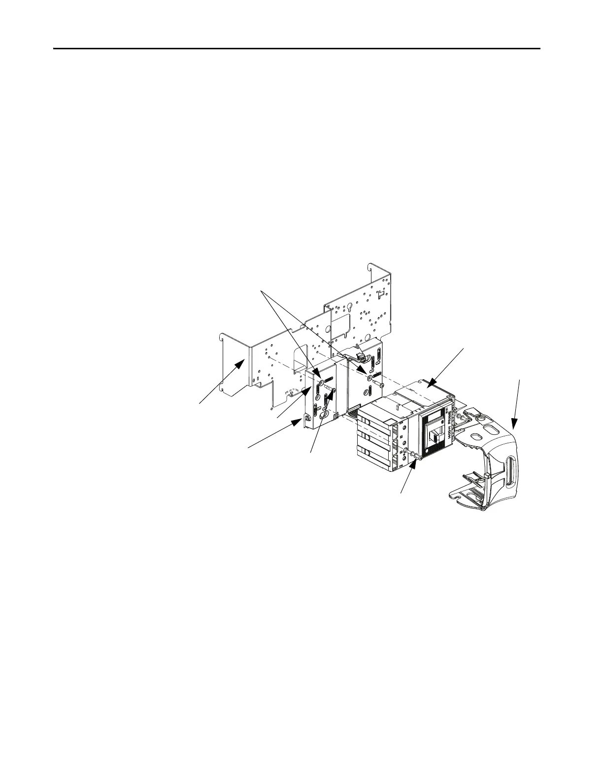
Install Circuit Breaker
Follow these steps to install the Bulletin 140G circuit breaker in a horizontal
handle unit.
1. Mount the circuit breaker base to the mounting plate by using #8-32 x
1.62 Pan head screws (G frame units); #8-32 x 0.81 Pan head screw (H
and J frame units).
Use the horizontal mounting holes (2100H).
2. Tighten to 18 lb•in (2.03 N•m)
3. Mount the circuit breaker to the base by using screws (included with the
circuit breaker), split lock washers, and flat washers (use washers from
the existing unit) and tighten to 10 lb•in (1.13 N•m).
4. Put the circuit breaker ON/OFF switch to the ‘ON’ position.
Mounting
Plate
Base
Circuit Breaker
bale
Supplied with Circuit Breaker
10 lb•in (1.13 N•m)
#8-32 Pan head screw
18 lb•in (2.03 N•m)
Adjustment
Screw
Horizontal Mounting
Holes 2100H

 Loading...


