Rockwell Automation Publication 2100-IN012G-EN-P - August 2016 25
Chapter 2
Installation Procedures
Location Planning
When planning the location for your CENTERLINE® MCC, consider the
following:
•Conduits
•Busways
• Overall height of installation area
•Alignment with other equipment
• Future needs
•Ambient temperature
The area must be level and the environment must be compatible with the
NEMA enclosure rating of the equipment
Documentation packages shipped with assembled MCCs include an MCC
elevation drawing and an MCC floor plan layout.
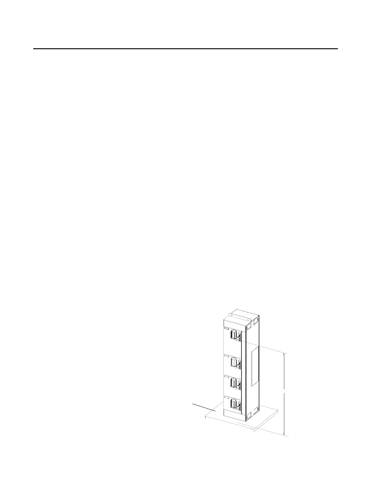
Height Considerations
If the MCC is equipped with optional external mounting channels or is
mounted on a pad, the height from the floor to the center of the top handles
must be checked for compliance with NFPA 70 National Electrical Code
(NEC) Article 404.8 and UL Standard 845. If the distance from the floor to
the center of the highest handle is greater than 6.7 ft (2042.16 mm), add a unit
operating handle extender (catalog number 2100H-NE1).
Figure 9 - Height Planning Dimensions
Height of Handle
Cement Pad
Floor Line
6.7 ft (2042.16 mm)
Maximum

 Loading...


