116 Rockwell Automation Publication 2100-IN012G-EN-P - August 2016
Appendix A Bulletin 140G Unit Assembly Instructions
5. Tighten to 18 lb•in (2.03 N•m).
6. Mount the circuit breaker to the base by using screws (included with the
circuit breaker), split lock washers, and flat washers (use washers from
the existing unit).
7. Tighten to 10 lb•in (1.13 N•m).
8. Put the circuit breaker ON/OFF switch to the ‘ON’ position.
9. Install the bale on to the circuit breaker base.
The bale snaps into place on both sides of the circuit breaker base. (If the
bale does not snap in easily, check the orientation of the bale.)
TIP The wires from internal accessories on the right side of the circuit breaker
are routed under the circuit breaker in the ‘trough’ in the base so they exit
on the left.
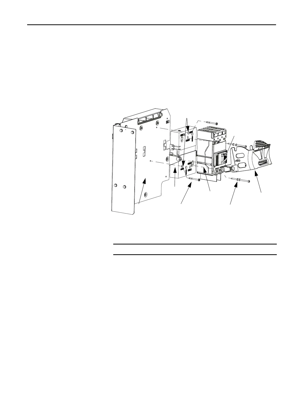
Mounting
Plate
Base
Circuit Breaker
bale
Supplied with Circuit Breaker
10 lb•in (1.13 N•m)
#8-32 Pan head screw
18 lb•in (2.03 N•m)
The circuit breaker and the mounting plate are
not included in the repair kit.
Vertical Mounting Holes
2100V
Circuit Breaker
On/Off Switch
IMPORTANT The circuit breaker must be in the ‘ON’ position to install the bale.

 Loading...


