Rockwell Automation Publication 2100-IN012G-EN-P - August 2016 21
General Information Chapter 1
NEMA Type 1 w/
gasket or Type 12
Series E...J
(7)
0.5
(2)
N or later — — — ——
1.0 or
larger
A-E
(4)
—— ————
(8)
F-L
(4)
———————
M or later———————
NEMA Type 1 w/
gasket or Type 12
Series K or later
0.5
(2)
N or later ———————
1.0 or
larger
A-L
(4)
—— ————
(8)
M or later ———————
(1) When installing unit in topmost location in vertical sections, care must be taken to comply with the National Electric Code 6.7 ft (2000 mm) unit handle-to-floor height limitation. A unit operating
handle extender (catalog number 2100-NE1) that provides 3 in. (76.2 mm) added height flexibility is available.
(2) When CENTERLINE 2100, 0.5 space factor or Space Saving NEMA Starter plug-in units are ordered unassembled or ordered for existing sections, order a centralized wiring diagram holder kit (catalog
number 2100H-WDH).
(3) Permits installation of 0.5 space factor or Space Saving NEMA Starter plug-in units in existing series E...J CENTERLINE 2100 vertical sections.
(4) Replacement and renewal parts are no longer supported. Contact Rockwell Automation LV MCC Technical Support at 1.440.646.5800 and follow the prompts to Allen-Bradley > Low Voltage Motor
Control Centers > Post Shipment Support.
(5) Required only if series F or later, 1.0 space factor or larger CENTERLINE 2100 unit is installed in topmost location of series A...E vertical sections.
(6) For more information regarding possible door hinge requirements, contact Rockwell Automation LV MCC Technical Support at 1.440.646.5800 and follow the prompts to Allen-Bradley > Low Voltage
Motor Control Centers > Post Shipment Support.
(7) Series E...J sections cannot accommodate 0.5 space factor or Space Saving NEMA Starter plug-in units in bottom-most unit location.
(8) A ground strap can be used to ground units rather than installing a ground bus. Refer to the CENTERLINE 2100 Motor Control Centers (MCC) Units with Vertical Operating Handles Installation
Instructions, publication 2100-IN014
.
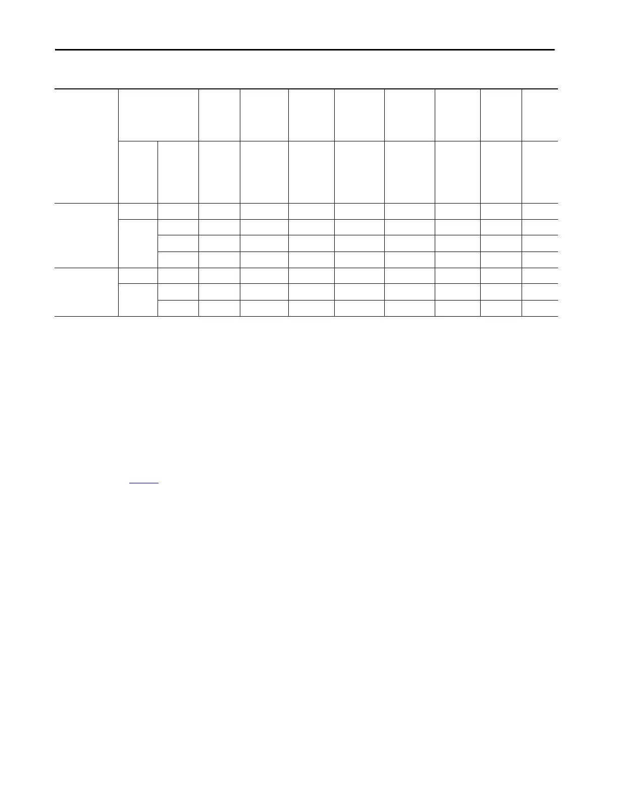
Table 4 - MCC Modifications for Unit and Structure Compatibility
If Mounted in this
Type of
Section
(1)
,
(2)
Plug-in Units No
Additional
Parts
Required
Requires
Style 1 Unit
Support Pan
Requires
Style 3 Unit
Support
Pan
Requires
Style 3 Unit
Support Pan
w/ Bushing
Requires
Alternate
Top
Horizontal
Wireway Pan
Requires
Door
Gasketing
Kit
Requires
Retrofit
Kit
(3)
Requires
Ground
Bus Kit
Space
Factor
Series — 2100H-UAJ1 2100H-
UA12100H-
UJ1
2100H-
USPA1
2100H-USPJ1
2100H-
NA4A1
2100H-NA4J1
2100H-
NA4A2
2100H-NA4J2
2100-GJ10 2100H-R1
2100H-R2
2100H-
GS1

 Loading...


