MCC MCC MCC
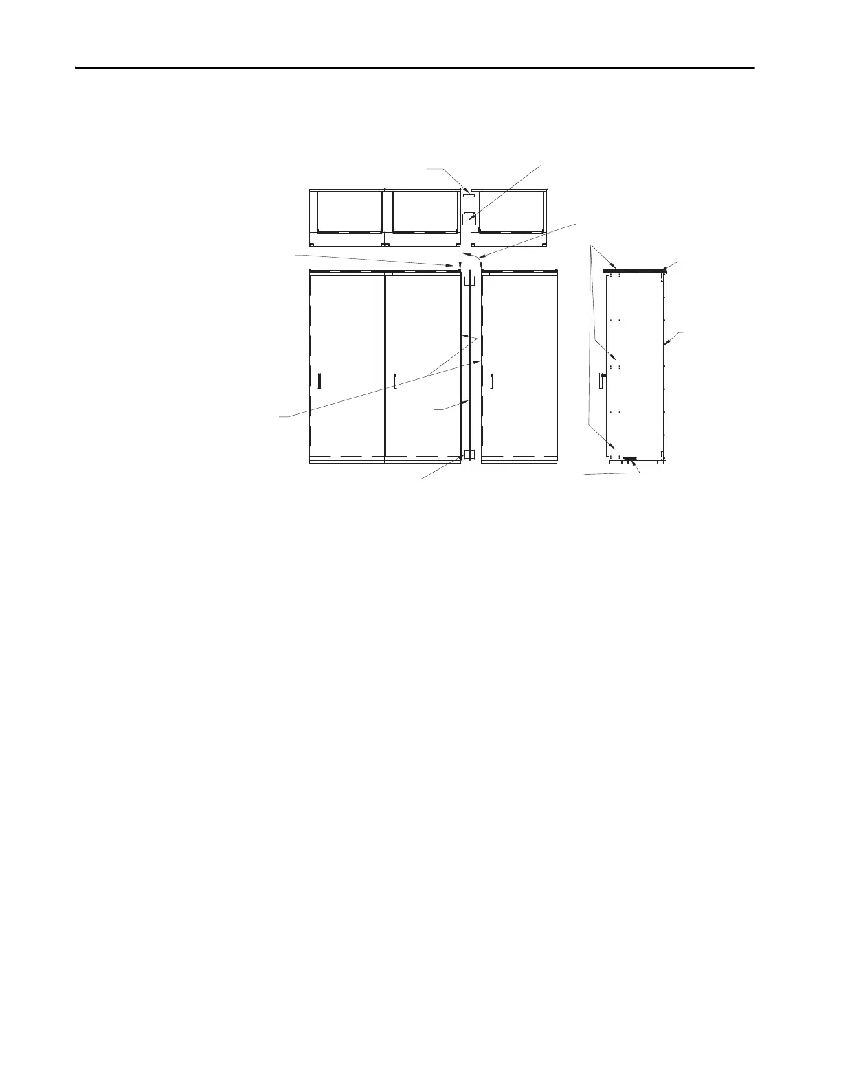
Cabinet Spacer
(2) 0.25 in. (6 mm) x 0.50 in. (12.7 mm) Taptites
Cabinet Spacer
(2) 0.25 in. (6 mm) x 0.50 in. (12.7
mm) Taptites
(2) 0.25 in. (6 mm) x 0.50 in. (12.7 mm) Taptites
Cabinet Spacer
(2) 0.25 in. (6 mm) x 0
in. (12.7 mm)
Tap tites
Gasket
Gasket
Wireway Extensions
(2) or (4) 0.25 in. (6 mm) x 0.50 in. (12.7
mm) Taptites
(2) wireway extensions required for 15 in. (381 mm) deep.
(2) wireway extensions required for 20 in. (508 mm) deep.
(1) 0.25 in. (6 mm) -20 x 0.70 in. (17.78 mm) taptite per wireway extension.
Remove left-hand driphood angle and remount after the
adjacent driphood has been drilled out.
Remove right-hand driphood angle and
discard. Drill out (5) 0.172 in. (4.36 mm)
diameter holes to 0.25 in. (6 mm) diameter in
driphood.
Remove the right-hand and left-hand side
plates before joining sections. The gasket is
across the top of the driphood and down
the backplate on one of the adjoining
sections.
Gasket

 Loading...


