Introducing the Remote I/O Adapter
Module
Chapter 1
1-2
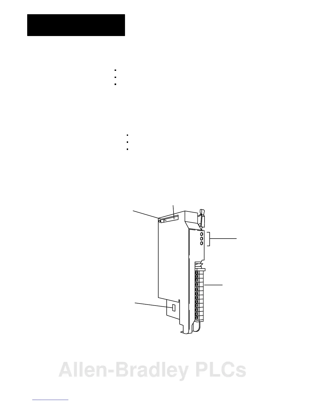
The remote I/O adapter module consists of four major components:
diagnostic indicators
module switch assemblies
field wiring arm
Diagnostic Indicators
Diagnostic indicators are located on the front panel of the adapter module
(Figure 1.1). They show both normal operation and error conditions in
your remote I/O system. The indicators are:
ACTIVE (green)
ADAPTER FAULT (red)
I/O RACK FAULT (red)
A complete description of these indicators and how to use them for
troubleshooting is explained in chapter 4.
Figure 1.1
Remote
I/O Adapter Module
Diagnostic
Indicators
Switch S1
Configuration
Jumpers
Field
Wiring
Arm
10796I
Switch S2
Hardware Components
Allen-Bradley PLCs
 Loading...


