Introducing the Remote I/O Adapter
Module
Chapter 1
1-3
Module Switch Assemblies
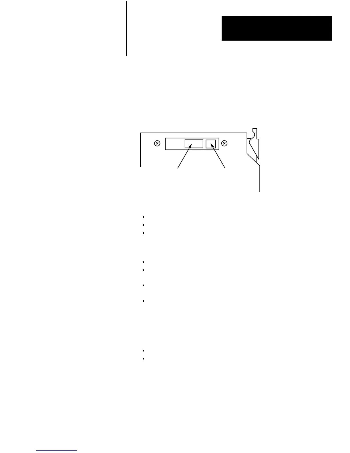
You must set two switch assemblies to configure your adapter module.
Figure 1.2 shows the location of the switches.
Figure 1.2
Switch
Locations
Switch Assembly
(S1)
Switch Assembly
(S2)
The S1 Assembly is used to select:
the first I/O group number
the I/O rack number
I/O scanner communication with or without complementary I/O
(for PLC-2 family processors)
The S2 Switch Assembly selects:
a specific baud rate based on the maximum I/O chassis distance
I/O scanner communication with or without complementary I/O
(for PLC-2 family processors)
scan - processor will scan all slots in the chassis, or all but the last
four slots in the chassis
link response - establishes series B emulation response time
required for compatibility with PLC-2 and PLC-3 scanners.
Field Wiring Arm
The field wiring arm (cat. no. 1771-WB) provides connection points for:
I/O communication cables
a user-supplied I/O chassis restart pushbutton
The field wiring arm (Figure 1.1) pivots on the front of the chassis to
connect with the module’s printed circuit board. This feature allows you to
remove the adapter module without disconnecting the system wiring.
In this chapter we discussed the functions and hardware components of the
Remote I/O Adapter Module.
Summary
 Loading...


