Installing Your Module
Chapter 2
2-9
After setting the adapter module switch assemblies, you must also
set the I/O chassis backplane switches
Setting the Backplane Switch Assembly
The backplane switch assembly is located on the backplane of the I/O
chassis. You use it to select:
the last state of all outputs
the processor restart lockout feature
1/2-, 1- or 2-slot addressing
the last chassis in the I/O system (for PLC-2 family processors)
Refer to the table below for backplane switch setting illustrations for the
various processors.
For Processor: Refer to:
PLC2 Figure 2.8, page 29
PLC3 Figure 2.9, page 210
PLC5 Figure 2.10, page 210
PLC5 remote configuration Figure 2.11, page 211
PLC5/250 Figure 2.12, page 211
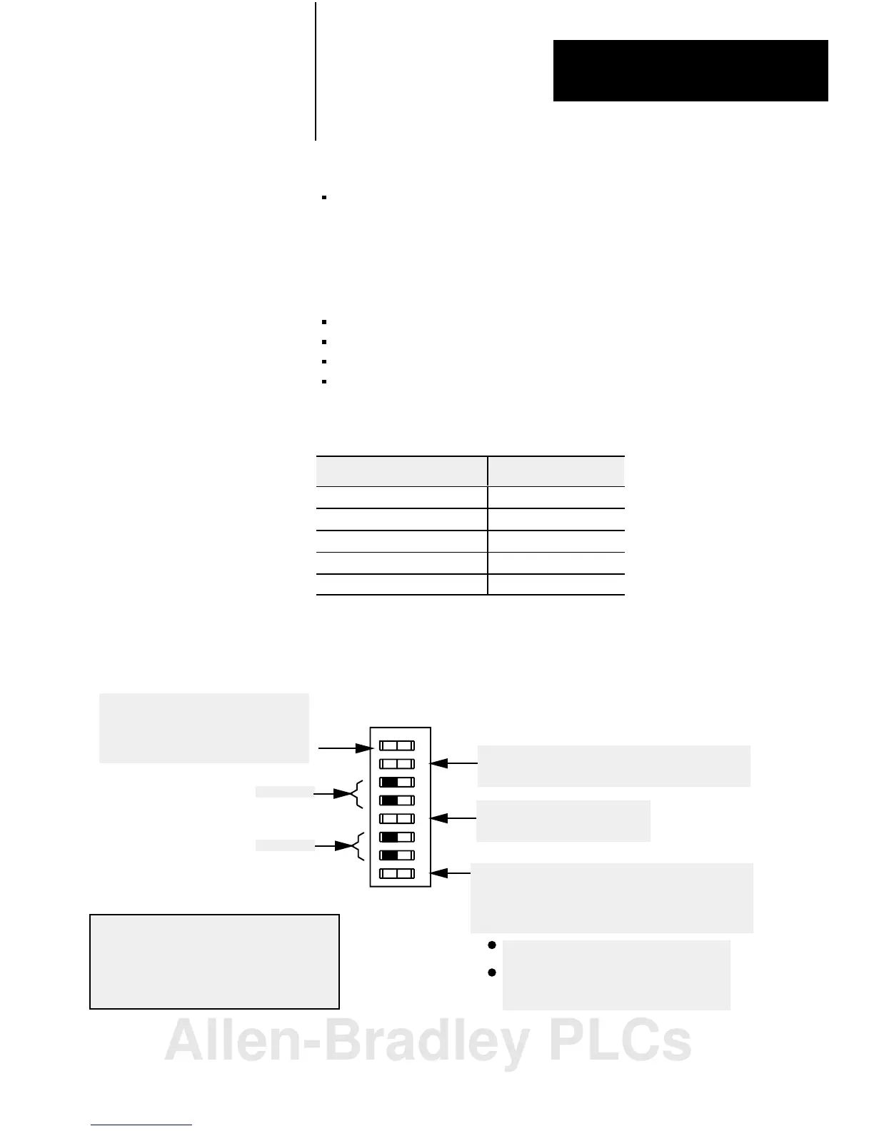
Figure 2.8
I/O
Chassis Backplane Switch Assembly Settings for Remote Adapter
Module in PLC2 Family Processor System
Processor Restart Lockout
When ON, processor can restart I/O chassis
When OFF, I/O chassis must be restarted at the chassis.
Addressing Switch
ON 1slot addressing selected
OFF 2slot addressing selected
Last State Switch
When ON, outputs of this chassis remain
in last state.
When OFF, outputs of this I/O chassis are
deenergized when a fault is detected.
Always OFF
Last Chassis Switch
ON Chassis does not contain the highest numbered I/O
group for the associated rack number
OFF Chassis does contain the highest numbered I/O
group for the associated rack number
If you have only a primary chassis, set this
switch to OFF.
If you have both primary and complementary
chassis, set the primary chassis to ON and the
complementary chassis to OFF.
10802I
ATTENTION: Set switch 1 to the OFF position
to deenergize outputs wired to this chassis when a
fault is detected. If switch 1 is set to the ON
position, outputs connected to this chassis remain
in their last state when a fault occurs and machine
motion may continue after fault detection.
O
O
12 3456 78
N
F
F
Always OFF
Setting
the I/O Chassis
Switches
Allen-Bradley PLCs
 Loading...


