Installing Your Module
Chapter 2
2-8
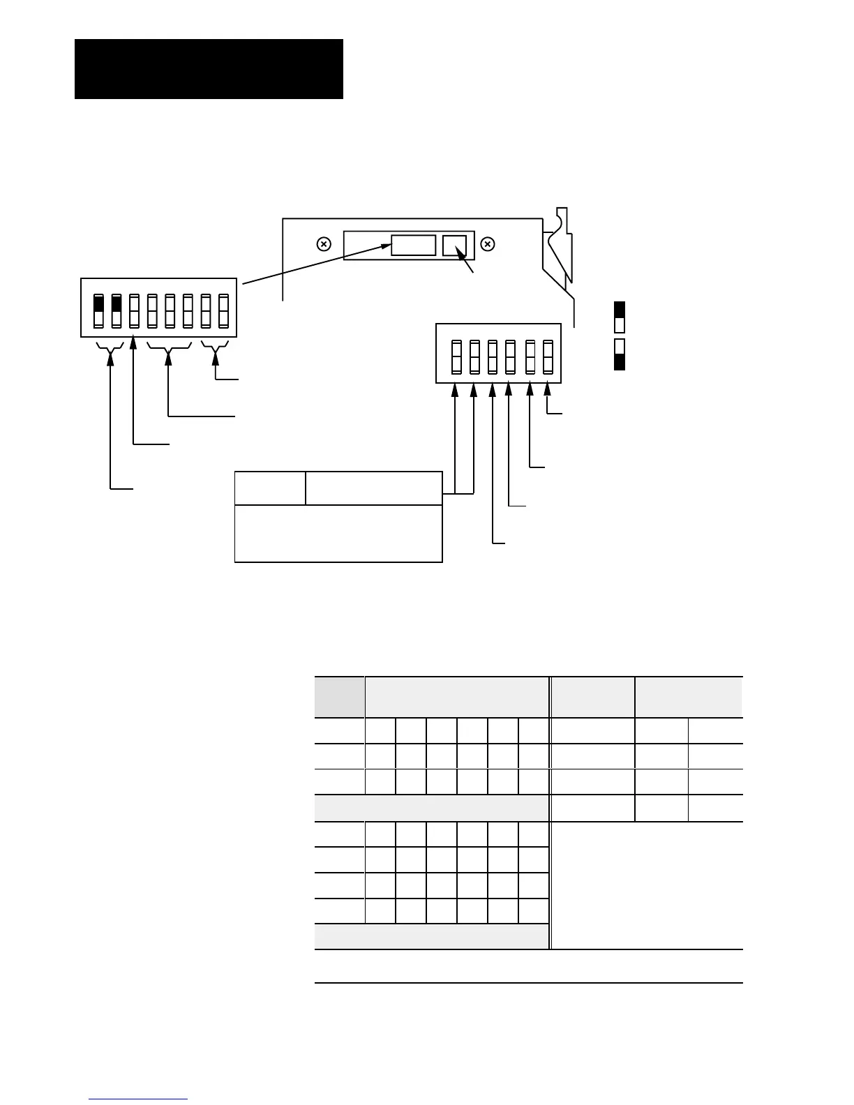
Figure 2.7
Module
Switch Assembly Settings for PLC5 Family Processors W
ith
Complementary I/O
12345678
O
N
O
F
F
First I/O group number
(Table 2.F)
I/O rack number
(Table 2.F)
Address Switch Assembly
(S1)
Switch Assembly
(S2)
Pressed in at top
Closed (ON)
Pressed in at bottom
Open (OFF)
Always
ON
ON Primary chassis
OFF Complementary chassis
ON Primary chassis
OFF Complementary chassis
O
N
O
F
F
1234
56
Link Response on for series B emulation
Scan on for all but last 4 slots
off for all slots
off for unrestricted
10801I
Switch Position
1 2
ON OFF 57.6K Baud 10,000ft
OFF OFF 1
15.2K Baud 5,000ft
ON ON Not Used
Maximum
I/O
chassis distance(see note)
OFF
ON 230.4K Baud 2,500ft
Note: PLC5/15 and 5/25 processors
operate at 57.6K baud only.
Off
Table 2.F
I/O
Rack Selection for PLC5 Family Processors with Complementary I/O
I/O
Rack #
Switch
1 2 3 4 5 6
1st I/O Group
Number
Switch Selections
7 8
01 On On On On On Off 0 On On
02 On On On On Off On 2 On Off
03 On On On On Off Off 4 Off On
6 Off Off
04 On On On Off On On
05 On On On Off On Off
06 On On On Off Off On
07 On On On Off Off Off
See
note below
Note: PLC5/11
can scan rack 03.
PLC5/20, PLC5/30, PLC5/40, PLC5/60 can scan racks 0107.
 Loading...


