Troubleshooting
Chapter 4
4-3
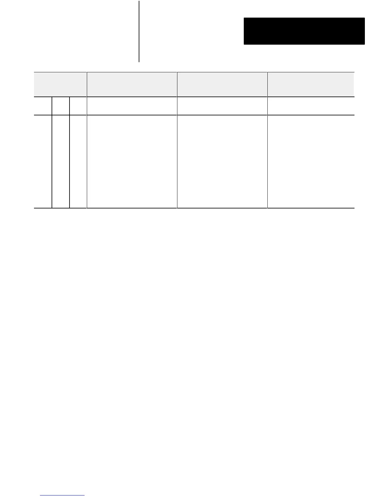
Recommended ActionProbable CauseDescription
Indicators
Active Adapter I/O
Fault Rack
Blink On Off Module identification line fault Excessive noise on backplane Verify power supply and chassis
grounding
Off Off Off Module not communicating Power supply fault
Wiring from scanner to adapter module
disrupted
Scanner not configured properly
One faulted chassis within a rack group
address causing scanner/distribution
panel to fault all chassis in rack group
address (when in disable search mode)
Check power supply, cable
connections, and make sure adapter
module is fully seated in chassis.
Correct cable and wiring defects
Refer to publication 1772-2.18 for
scanner configuration
Check sequentially from the first
module to the last module to pinpoint
fault; correct any faults and proceed to
the next chassis
1. You must select the operating mode of the remote I/O adapter module as outlined in the publication furnished with the remote I/O scanner/distribution
panel, remote I/O scanner-program interface module, or I/O scanner-message handling module. Pay close attention to the disable search mode in
the 1771-SD, -SD2.
2. The I/O chassis is in faulted mode as selected by the last state switch on the chassis backplane.
3. Cycling power clears the block-transfer request queue. All pending block transfers are lost. Your program must repeat the request for block transfers
from the chassis.
4. If a fault occurs and the processor is in the run mode but is actually operating in the dependent mode, the chassis fault response mode is selected by
the last state switch on the chassis backplane.
5. The I/O chassis is in faulted mode as selected by the last state switch on the chassis backplane.
6. If excessive chassis faults occur, check switch SW2, position 6 for the OFF position.
In this chapter you learned how to use the indicators on the front of the
module to troubleshoot your module.
Summary
 Loading...


