Appendix
B
B-1
Settings for 1771-AS and 1771-ASB
Series A, B and C Remote I/O Adapters
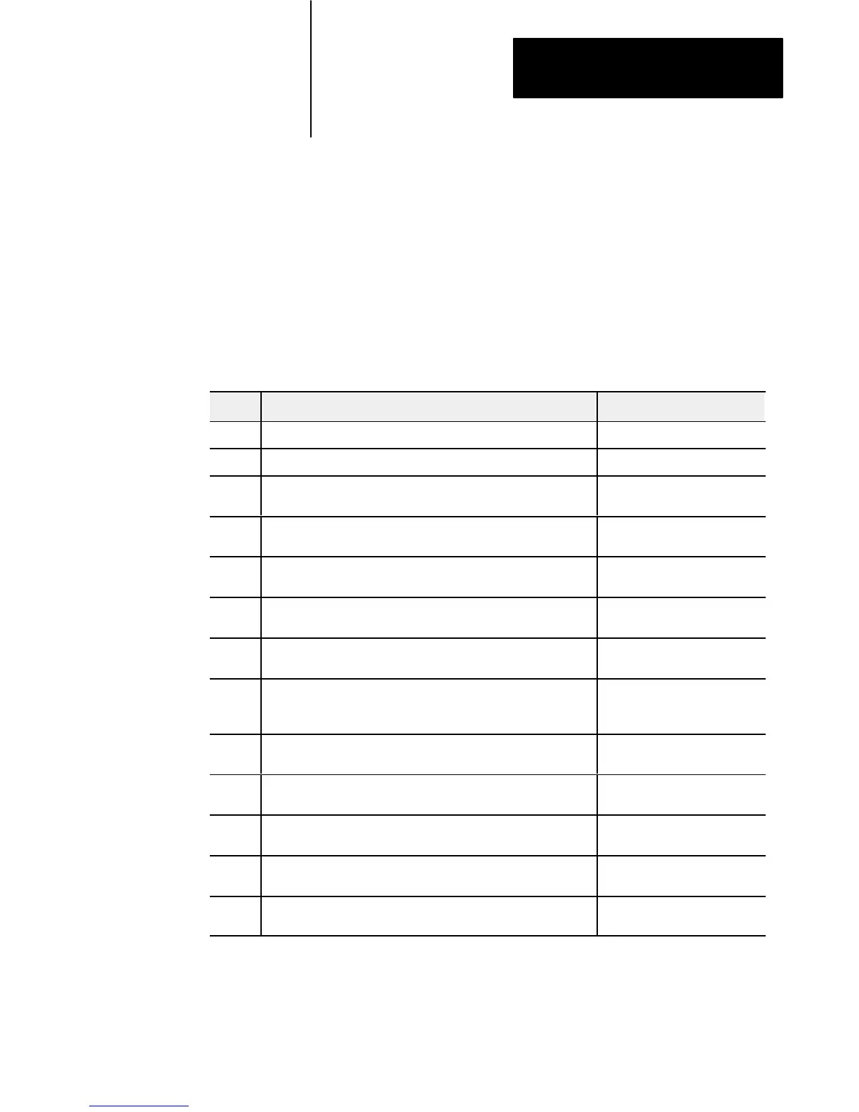
This appendix provides information on previous remote I/O adapters
supplied by Allen–Bradley. The following table lists the adapter and
respective figure reference.
Figure Description Applies to:
B.1 Keying Diagram for 1771-ASB series A, B and C 1771-ASB series A, B and C
B.2 Keying Diagram for 1771-AS 1771-AS
B.3 Field Wiring Arm Connection for 1771-AS, -ASB series A, B and C
1771-AS
1771-ASB series A, B and C
B.4
Module Switch Assembly Settings for 1771-AS, -ASB series A and B
Adapter for PLC-2 Family Processors
1771-AS
1771-ASB series A, B
B.5
Module Switch Assembly Settings for 1771-ASB series C Adapter for
PLC-2 Family Processors
1771-ASB series C
B.6
Module Switch Assembly Settings for 1771-AS and 1771-ASB series
A and B Adapters for PLC-3 Family Processors
1771-AS
1771-ASB series A, B
B.7
Module Switch Assembly Settings for 1771-ASB series C Adapters for
PLC-3 Family Processors
1771-ASB series C
B.8
Module Switch Assembly Settings for 1771-AS and 1771-ASB series
A and B Adapters for PLC-5 Family Processors without
Complementary I/O
1771-AS
1771-ASB series A, B
B.9
Module Switch Assembly Settings for 1771-ASB series C Adapters for
PLC-5 Family Processors without Complementary I/O
1771-ASB series C
B.10
Module Switch Assembly Settings for 1771-AS, -ASB series A and B
Adapters for PLC-5 Family Processors with Complementary I/O
1771-AS
1771-ASB series A, B
B.11
Module Switch Assembly Settings for 1771-ASB series C Adapters for
PLC-5 Family Processors with Complementary I/O
1771-ASB series C
B.12
I/O Chassis Backplane Switch Assembly Settings for 1771-AS
Remote Adapter Module in PLC-2 Family Processor System
1771-AS
B.13
I/O Chassis Backplane Switch Assembly Settings for 1771-AS
Remote Adapter Module in PLC-3 Family Processor System
1771-AS
General Information
 Loading...


