Installing Your Module
Chapter 2
2-3
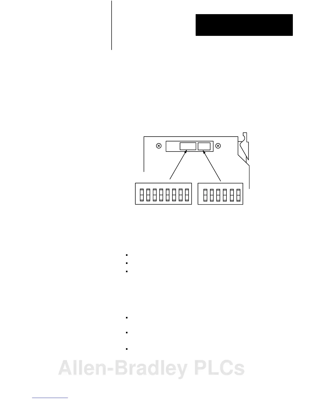
Set switch assemblies S1 and S2 (Figure 2.3) with a blunt, pointed
instrument such as a ball-point pen. Do not use a pencil; the lead could
break off and jam the switch.
This publication describes switches as being either on or off. The words
ON and OFF should be printed on the switch assemblies. If a switch
assembly has the word OPEN printed on it, the word OPEN corresponds
to OFF.
Figure 2.3
S1
and S2 Switch Assembly Locations
12345678
O
N
O
F
F
O
N
O
F
F
1234
Address Switch Assembly
(S1)
Switch Assembly
(S2)
56
Address Switch Assembly (S1)
You use this switch assembly to select:
the first I/O group number
the I/O rack number
primary/complementary – I/O scanner communication with or
without complementary I/O (for PLC-2 and PLC-5 family
processors)
Switch Assembly (S2)
You use this switch assembly to select:
baud – a specific baud rate based on the maximum I/O chassis
distance
primary/complementary – I/O scanner communication with or
without complementary I/O (for PLC-2 family processors)
scan - select whether the processor will scan all slots in the
chassis, or all but the last four slots in the chassis
Setting the Module Switches
Allen-Bradley PLCs
 Loading...


