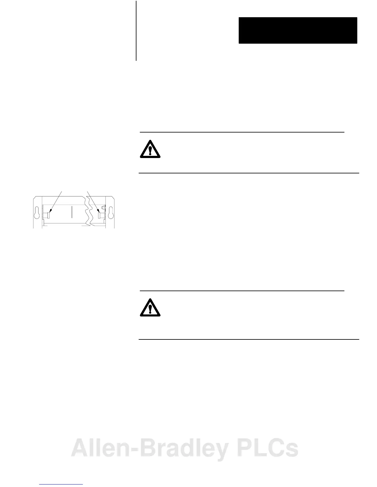
front of chassis
lockingbar pins
12453I
Installing Your Module
Chapter 2
2-15
Once you’ve determined the power requirements, keying, and wiring for
your adapter module, and have set the appropriate switch assemblies, you
can use the following procedure to install it.
Refer to the Programmable Controller Grounding and Wiring Guidelines
(publication 1770-4.1) for proper grounding and wiring methods to use
when installing your module.
ATTENTION: Remove system power before removing or
installing your module in the I/O chassis. Failure to observe
this warning could damage module circuitry and injure people.
1. Remove power from the I/O chassis before inserting (or removing)
the module.
2. On chassis equipped with a chassis locking bar, pull the locking-bar
pins to release the locking bar and swing it up.
3. Insert the module into slot.
4. Place the module in the plastic tracks on the top and bottom of the
leftmost slot. These slots guide the module into position.
5. Press firmly and evenly to seat the module in its backplane
connectors.
ATTENTION: Do not force the module into the backplane
connector. If you cannot seat the module with firm pressure,
check the alignment and keying. Forcing the module can
damage the backplane connector or the module.
6. Snap the chassis locking bar (or locking latch on earlier chassis) over
the top of the module to secure it. Make sure the locking pins on the
locking bar are fully engaged.
Note: The chassis locking bar will not close if all modules are not
properly seated.
7. Swing field wiring arm up into place and press firmly until it latches.
8. Reapply system power and check for proper operation.
Module Installation
Allen-Bradley PLCs
 Loading...


