Installing Your Module
Chapter 2
2-14
If this is the last remote I/O adapter on the link, you must use a terminating
resistor to terminate both ends of the remote I/O link (scanner end and last
adapter end). The size of the terminator is determined by the system
configuration.
Older configurations use a 150 ohm resistor at both ends. With newer
products that can support it, you can use an 82 ohm terminator at both
ends. The 82 ohm terminators provide “extended node” capability which
allows you to have up to 32 physical devices on the RIO link. (The number
of logical racks capable of being addressed by the scanner is not affected.)
This allows 1/4, 1/2 and 3/4 racks, Dataliners, Redipanels and Panelview
devices to be attached to the link.
ATTENTION: Devices that are operating at 230.4K Baud must
have 82 ohm terminators in place for proper operation.
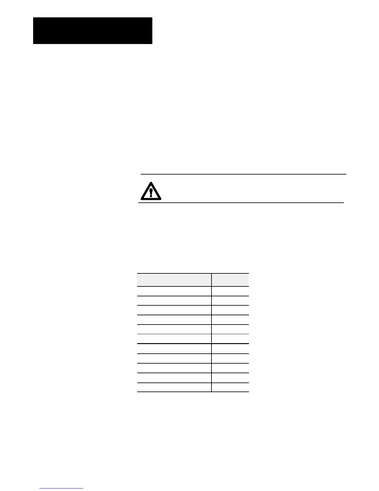
Certain products are not compatible with the extended node capabilities
obtained with the use of the 82 ohm terminator resistors. These products
are listed below.
Table 2.G
Noncompatible
Products
Device Series
Scanners
1771SN All
1771SD All
1772SD2 All
1775SR All
1775S4A All
1775S4B All
Adapters 1771AS All
1771ASB Series A
1771DCM All
Miscellaneous 1771AF All
1771AF1 All
Installing the Terminator
Compatibility of 1771
Remote I/O Products with
Extended Node Numbers
 Loading...


