Installing Your Module
Chapter 2
2-13
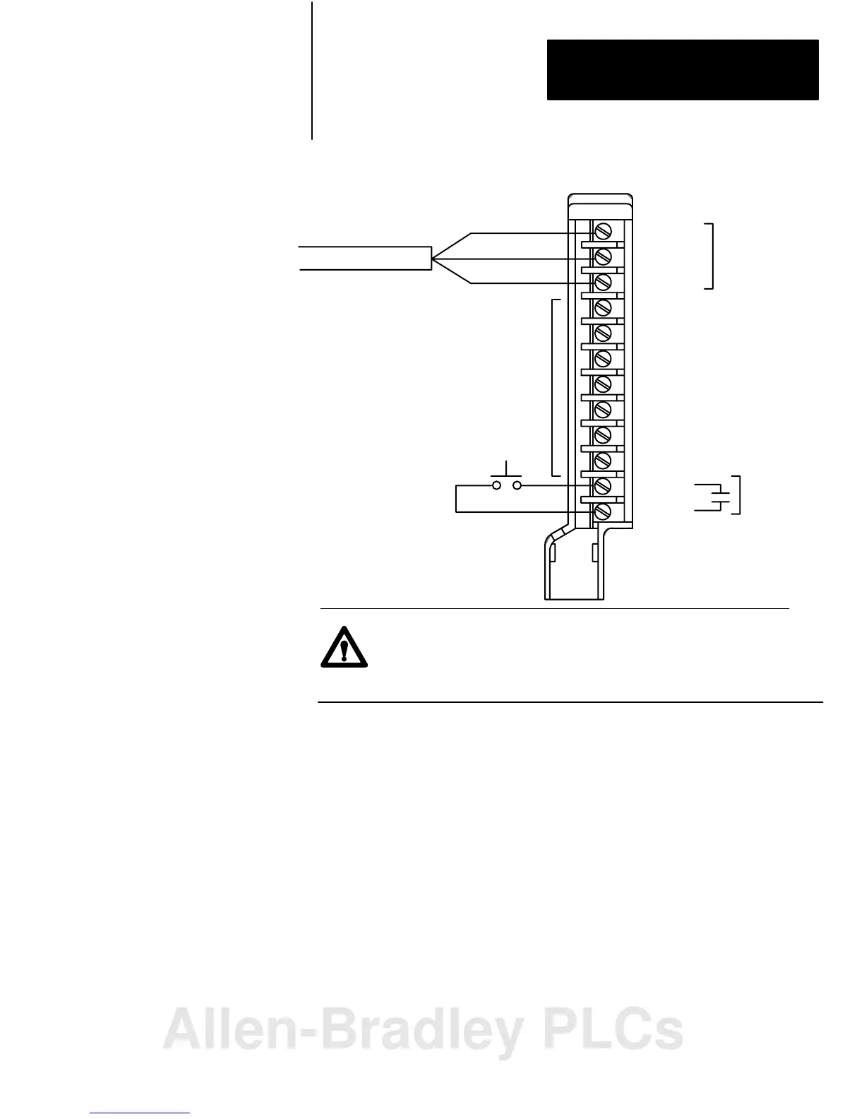
Figure 2.14
Field
W
iring Arm Connection Diagram
1 Line 1
2 Shield
3 Line 2
4 No connection
5 No connection
6 No connection
7 No connection
8 No connection
9 No connection
10 No connection
11 In
12 Ret
Reset
User supplied
I/O rack restart
pushbutton
AllenBradley Cable (cat. no. 1770CD)
Blue
Shield
Clear
1
2
3
4
5
6
7
8
9
10
11
12
Cable
17343
ATTENTION: Do not make connections to
terminals 4 through 10. These terminals are
connected
internally (1
to 4, 2 to 5 and 3 to 6)
and cannot be used for any other purpose.
Remote I/O Cable
ATTENTION: Do not remove or insert the adapter module
from the I/O chassis while system power is on. Otherwise, you
may damage module circuitry.
Terminals 1 and 4, 2 and 5, and 3 and 6 are internally connected on the
module. If you use these terminals (4, 5, and 6) for connection of
additional adapter modules, you disconnect the remaining adapter modules
in the series connection when you disconnect the remote I/O adapter
module wiring arm. If this is unsuitable for your application, make your
connections to terminals 1, 2, and 3 only.
Allen-Bradley PLCs
 Loading...


