Installing Your Module
Chapter 2
2-4
link response - unrestricted or series B emulation.
Certain scanner modules with multiple communication ports
require a delay in the link turnaround time to allow the central
processing unit (CPU) in the scanner sufficient time to service all
communication ports. Without this delay, some incoming
information may be missed while the scanner is servicing another
port. This results in multiple communication retries. To provide the
necessary delay, set the link response switch (position 5, switch
S2) to the ON position.
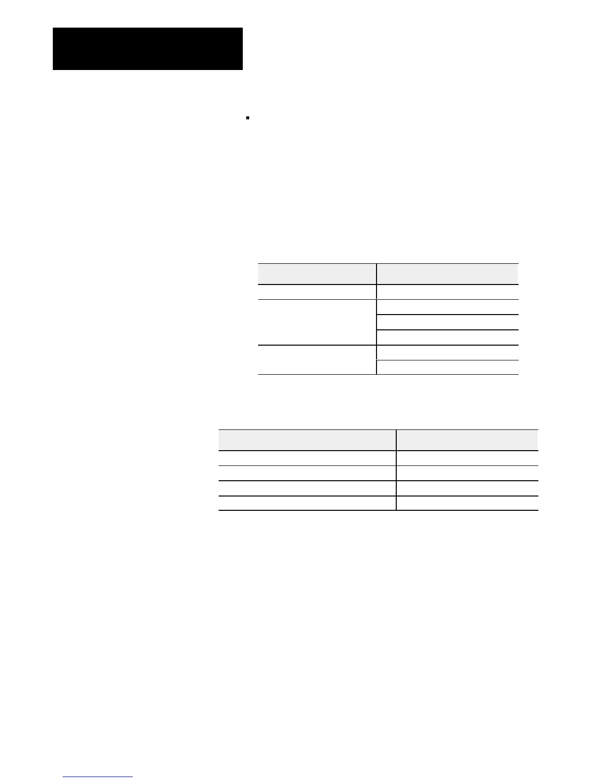
Scanner modules which require a delay are:
Programmable Controller Scanner Module
PLC2 1772SD2
1775S4A
PLC3
1775S4B
1775S5
PLC3/10
1775SR5
PLC3/10
1775SR
Refer to the Table below for Figure and page numbers of switch settings
for each processor family.
S1 and S2 Switch Settings for: Refer to:
PLC2 family processor Figure 2.4, page 25
PLC3 family processor Figure 2.5, page 26
PLC5 family processor without complementary I/O Figure 2.6, page 27
PLC5 family processor with complementary I/O Figure 2.7, page 28
 Loading...


