Chapter 3
Addressing Modes for Your Remote I/O
3-11
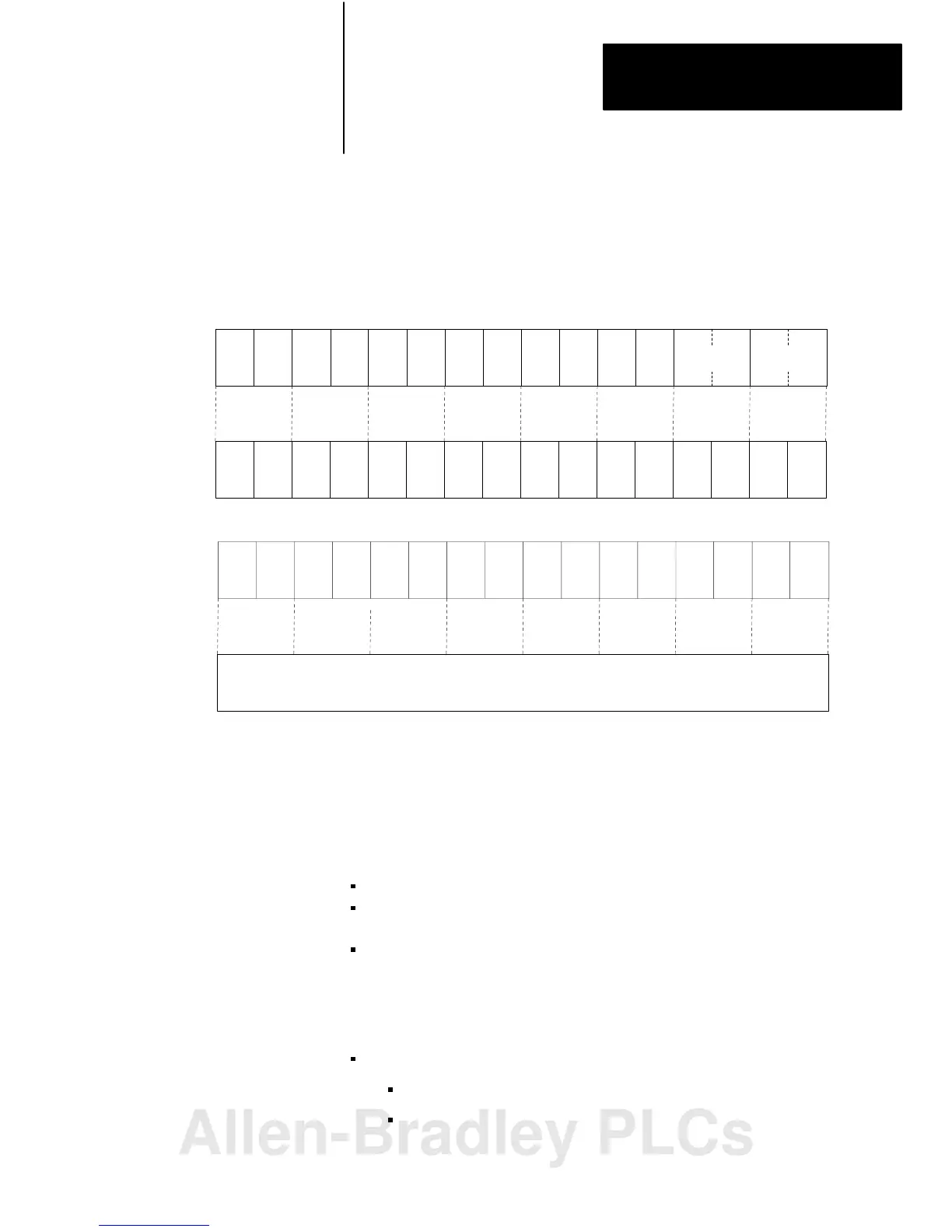
Module Placement with 2slot Addressing
Figure 3.9 shows possible module placement when configuring
complementary I/O with 2-slot addressing.
Figure 3.9
Complementary
I/O Configurations with 2slot Addressing
I
O
I
O
O
I
BT
BT
BT
Double-slot
BT
Double-slot
BT
E
M
P
T
Y
E
M
P
T
Y
E
M
P
T
Y
E
M
P
T
Y
E
M
P
T
Y
E
M
P
T
Y
E
M
P
T
Y
021 34567
O
021 34567
Example A
Exam
p
le B
Primary 16-slot
Chassis
I/O G roup
Number
Complementary
16-slot Chassis
Primary 16-slot
Chassis
I/O G roup
Number
Complementary
Chassis Not
A llo w e d
Except for Output
I = Input Module
O = Output Module
BT = Block transfer Module
1 Output modules use the same output image table bits
2 Can be 8-point input or output module or single-slot block transfer module
3 Must be empty if corresponding primary slot is block transfer module
2
13
13079
Outputs in the complementary chassis use the same bits in the output image table as
the outputs in the primary chassis.
3
3
333
8
I
8
8
O
8
16
16
O
8
O
8
8
8
O
8
O
8
O
8
I
8
I
8
O
8
O
8
O
8
O
8
O
8
I
16
16
I
16
O
16
I
16
I
16
I
16
I
16
I
16
I
16
O
16
O
16
O
16
O
16
O
16
O
16
Follow these guidelines when you select 2-slot addressing:
Place an 8-point output module opposite a 16-point input module.
An I/O group having a 16-point input and output module cannot have a
corresponding I/O group in the complementary chassis.
You can place an output module opposite another output module; they
reflect the same bits in the output image table.
You can use block-transfer modules in a complementary I/O system, with
these restrictions:
When using double-slot block-transfer modules:
The left slot of the complementary I/O group must be empty.
You can only place an 8-point output module (if any) in the right
slot of the complementary I/O group.
Allen-Bradley PLCs
 Loading...


