Velocity StepLogic™, Basic Logic and Timer/Counter Functions E-3
Velocity StepLogic Using Basic Logic Functions
Digital input and digital output parameters can be configured to use logic
to transition to the next step. Logic In1 and Logic In2 are defined by
programming parameters A051
-A054 [Digital Inx Sel] to option 23
“Logic In1” or option 24 “Logic In2”.
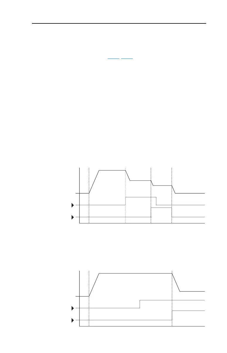
Example
• Run at Step 0.
• Transition to Step 1 when Logic In1 is true.
Logic senses the edge of Logic In1 when it transitions from off to on.
Logic In1 is not required to remain “on”.
• Transition to Step 2 when both Logic In1 and Logic In2 are true.
The drive senses the level of both Logic In1 and Logic In2 and
transitions to Step 2 when both are on.
• Transition to Step 3 when Logic In2 returns to a false or off state.
Inputs are not required to remain in the “on” condition except under
the logic conditions used for the transition from Step 2 to Step 3.
The step time value and the basic logic may be used together to satisfy
machine conditions. For instance, the step may need to run for a
minimum time period and then use the basic logic to trigger a transition
to the next step.
m
Lo
ic In
Lo
ic In
Frequenc
tar
Ste
Ste
Ste
Ste
m
Lo
ic In
Lo
ic In
Frequenc
tar
Ste
Ste

 Loading...


