EasyManua.ls Logo

Allen-Bradley PowerFlex 40P User Manual

Allen-Bradley PowerFlex 40P
200 pages
To Next Page IconTo Next Page
To Previous Page IconTo Previous Page
Page #95 background imageLoading...
Page #95 background image
Programming and Parameters 3-49
Enhanced Program Group
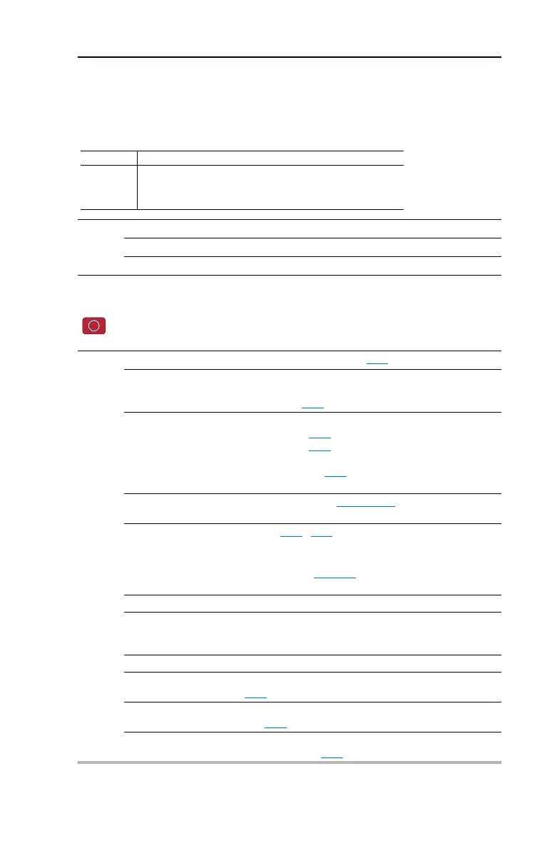
E201 [LED Display Opt]
Selects which parameters can be viewed by the drive’s LED interface.
Values Default: 2
Min/Max: 0/3
Display: 1
E201 Option Parameter Set
0
1
2
3
All Basic Display (Group b) and Advanced Display (Group d) parameters
All Basic Display Group (b001-b029) parameters
Basic Display Group parameters b001-b007 and b010
Basic Display Group parameter b001-b004
E202 [Digital Term 3]
Stop drive before changing this parameter.
Sets the function of I/O Terminal 03.
Options 0 “Start Source” (Default) Input functions as defined by P036
[Start Source].
1 “Acc/Dec Sel1” If active, can determine which Accel/Decel time will be used
for all ramp rates except jog. Can be applied to one input
only. Refer to A067
[Accel Time 2] for details.
2 “Jog” When input is present, drive accelerates according to the
value set in A079
[Jog Accel/Decel] and ramps to the
value set in A078
[Jog Frequency].
When input is removed, drive ramps to a stop according to
the value set in A079
[Jog Accel/Decel].
A valid “Start” command will override this input.
3 “Aux Fault” When enabled, an F2 Auxiliary Input
fault will occur when the
input is removed.
4 “Preset Freq” Refer to A070
- A077 [Preset Freq x].
Important: Digital Inputs have priority for frequency control
when programmed as Preset Speed and are active. Refer to
the flowchart on page 1-27
for more information on speed
reference control priority.
5 “Reserved”
6 “Comm Port” When active, sets communications device as default start/
speed command source.
Can only be tied to one input.
7 “Clear Fault” When active, clears an active fault.
8 “RampStop,CF” Causes drive to immediately ramp to a stop regardless of how
P037
[Stop Mode] is set.
9 “CoastStop,CF” Causes drive to immediately coast to a stop regardless of
how P037
[Stop Mode] is set.
10 “DCInjStop,CF” Causes drive to immediately begin a DC Injection stop
regardless of how P037
[Stop Mode] is set.

Table of Contents

Other manuals for Allen-Bradley PowerFlex 40P

Question and Answer IconNeed help?

Do you have a question about the Allen-Bradley PowerFlex 40P and is the answer not in the manual?

Allen-Bradley PowerFlex 40P Specifications

General IconGeneral
Input Voltage200-240V AC, 380-480V AC, 500-600V AC
Control MethodSensorless Vector Control
Communication OptionsEtherNet/IP, DeviceNet
Enclosure TypeIP20, NEMA/UL Type 1
ProtectionOvervoltage, Undervoltage, Overcurrent, Ground Fault
Operating Temperature0 to 40 °C
Storage Temperature-40 to 60 °C
Humidity5% to 95% non-condensing
DimensionsVaries by model
WeightVaries by model
Amperage1.6 to 32 A
Power Rating0.5 - 30 HP (0.4 - 22 kW)

Summary

Preface

Overview

Provides basic information for installing, starting up, and troubleshooting the PowerFlex 40P Adjustable Frequency AC Drive.

Installation/Wiring

Opening the Cover

Instructions on how to remove the drive cover for access to internal components.

Mounting Considerations

Details on proper mounting orientation, clearances, and ambient temperature requirements.

AC Supply Source Considerations

Guidance on handling ungrounded distribution systems and disconnecting protective MOVs.

General Grounding Requirements

Information on connecting the drive to system ground and motor ground for safety.

Fuses and Circuit Breakers

Recommendations for branch circuit protection, including fuse and circuit breaker ratings.

Power Wiring

Guidelines for selecting and installing motor cable types and power wiring practices.

I/O Wiring Recommendations

Best practices for connecting control signals and digital/analog inputs and outputs.

Hardware Enable Circuitry

Procedure for configuring a hardware enable input for disabling the drive without software interpretation.

EMC Instructions

Requirements for complying with Electromagnetic Compatibility (EMC) directive for CE installations.

Start Up

Prepare For Drive Start-Up

Checklist for verifying connections, power, and settings before applying power to the drive.

Display/Fault Reset

Explains the drive's LED display and how to reset faults.

Drive Programming Tools

Lists available tools for drive programming and control, such as DriveExplorer.

Programming and Parameters

About Parameters

Explains the three types of parameters: ENUM, Numeric, and Bit.

Parameter Organization

Details the structure of parameters organized into Basic Display, Basic Program, Advanced Program, etc.

Basic Display Group

Describes parameters for viewing drive operating conditions and status.

Basic Program Group

Covers fundamental parameters for motor configuration and basic drive operation.

Advanced Program Group

Details parameters for advanced control, I/O configuration, and motor tuning.

Enhanced Program Group

Explains parameters for advanced logic, step control, and communication settings.

Advanced Display Group

Describes parameters for monitoring drive status, feedback, and fault codes.

Troubleshooting

Drive Status

Explains how drive status is monitored and indicated via the LED display.

Faults

Defines fault types and the general procedure for responding to drive faults.

Fault Descriptions

Lists and describes specific fault codes, their causes, and corrective actions.

Common Symptoms and Corrective Actions

Provides troubleshooting steps for common drive issues like motor not starting or unstable operation.

Supplemental Drive Information

Drive, Fuse & Circuit Breaker Ratings

Recommends AC line input fuse and circuit breaker information for UL and IEC requirements.

Accessories and Dimensions

Product Selection

Presents a table for selecting PowerFlex 40P drives based on input voltage, power, and enclosure type.

RS485 (DSI) Protocol

Network Wiring

Details the physical wiring requirements for connecting drives on an RS485 network.

Parameter Configuration

Lists parameters required to configure the drive for network operation.

Supported Modbus Function Codes

Identifies Modbus function codes supported by the drive for communication.

Encoder Usage and Position StepLogic Application

Encoder Usage

Explains how encoders are used for speed reference, PID feedback, and direct feedback.

Positioning Operation

Details how to configure and operate the drive's positioning functions using Step Logic.

PID Set Up

PID Loop

Explains the basic operation of the PID loop, including reference, feedback, and error calculation.

PID Reference and Feedback

Describes how to select sources for PID reference and feedback signals.

Plate Drive Installation Instructions

Introduction

Introduces the plate drive version without a heatsink for custom mounting.

General Requirements

Outlines general requirements for operating the drive with an external heatsink.

Heatsink Thermal Capacity

Specifies the required thermal capacity for the heatsink to ensure proper drive cooling.

Related product manuals