Appendix C
RS485 (DSI) Protocol
PowerFlex 40P drives support the RS485 (DSI) protocol to allow
efficient operation with Rockwell Automation peripherals. In addition,
some Modbus functions are supported to allow simple networking.
PowerFlex 40P drives can be multi-dropped on an RS485 network using
Modbus protocol in RTU mode.
For information regarding DeviceNet or other communication protocols,
refer to the appropriate user manual.
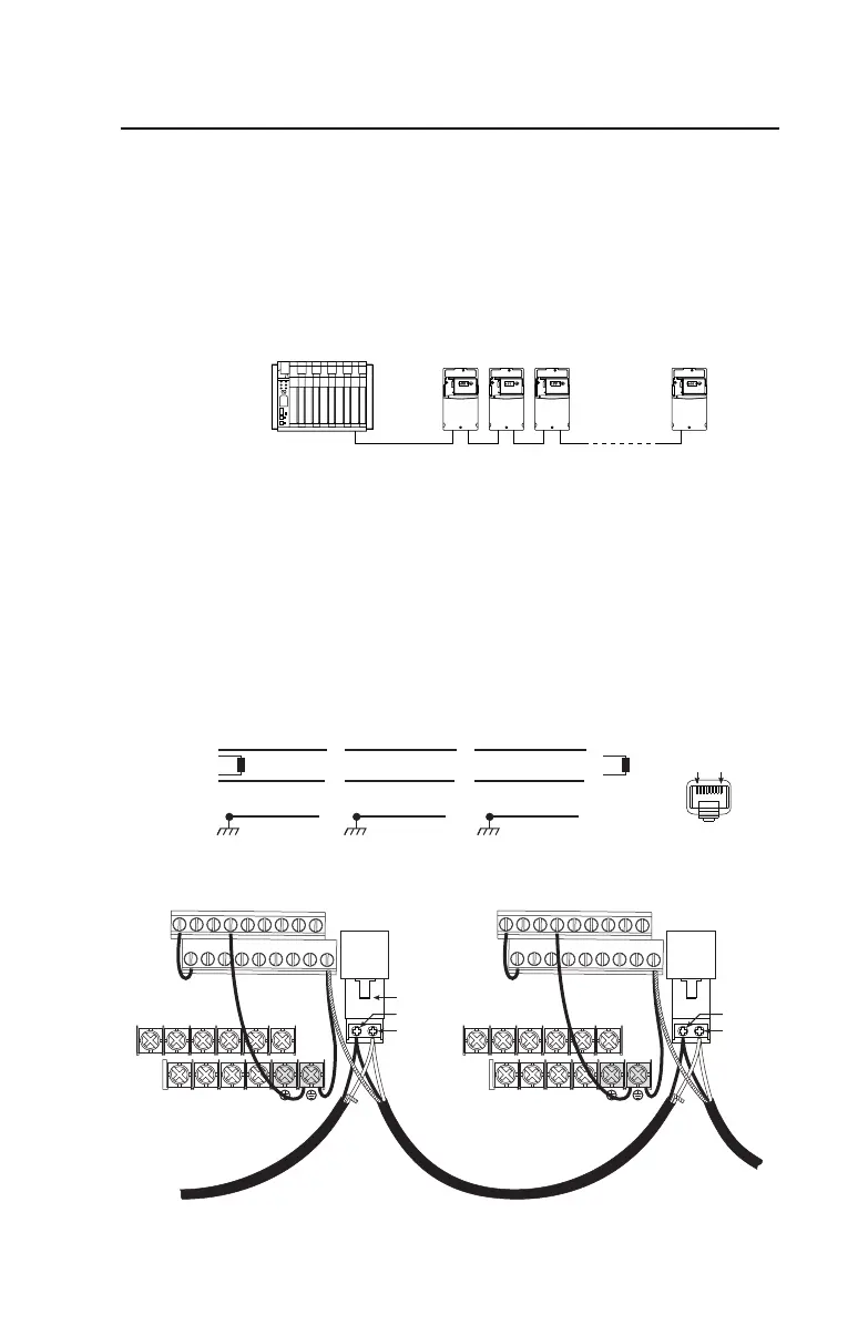
Network Wiring
Network wiring consists of a shielded 2-conductor cable that is
daisy-chained from node to node.
Figure C.1 Network Wiring Diagram
Controller
Master
PowerFlex 40P
Node 1
5
4
PowerFlex 40P
Node 2
5
4
PowerFlex 40P
Node "n"
5
4
TxRxD-
TxRxD+
TxRxD-
TxRxD+
TxRxD-
TxRxD+
NOTE: The shield is connected at ONLY ONE end of each cable segment.
Shield Shield Shield
120 ohm resistor
120 ohm resistor
X X X
FRONT
PIN 8
PIN 1
TxRxD+
TxRxD-
V/T2T/L3S/L2R/L1 U/T1
W/T3
BR+ BR-DC- DC+
01 02 03 04 05
11 12 13 14 15
06 07 08 09
16 17 18 19
RS485
(DPI)
AK-00-RJ45-TB2P
V/T2T/L3S/L2R/L1 U/T1 W/T3
BR+ BR-DC- DC+
01 02 03 04 05
11 12 13 14 15
06 07 08 09
16 17 18 19
RS485
(DPI)
TxRxD+
TxRxD-

 Loading...


