106 Rockwell Automation Publication 520-UM001G-EN-E - September 2014
Chapter 3 Programming and Parameters
Advanced Display Group (continued)
d389 [Units Traveled L] Related Parameter(s): d387
Stop drive before changing this parameter.
PowerFlex 525 only.
Displays the number of user-defined units traveled from the home position. See d387 [Position Status] for direction of travel.
Values Default: Read Only
Min/Max: 0.00/0.99
Display: 0.01
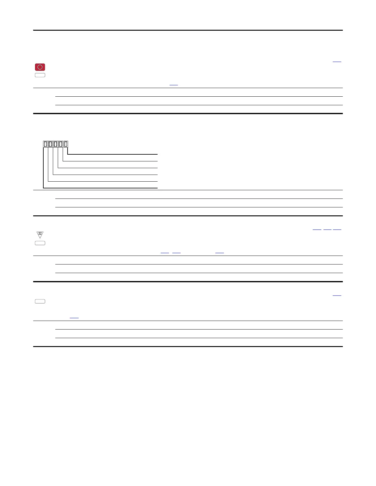
d390 [Fiber Status]
Present status of the Fibers features.
Values Default: Read Only
Min/Max: 0000/1111
Display: 0000
1 = Condition True, 0 = Condition False
Sync Hold Digit 1
Sync Ramp Digit 2
Traverse On Digit 3
Traverse Dec Digit 4
Not Used
d391 [Stp Logic Status] Related Parameter(s): P047, L180-L187
32 bit parameter.
PowerFlex 525 only.
Displays the current step of the Step Logic profile as defined by parameters L180...L187 [Step Logic x] when P047 [Speed Reference1] is set to 13 “Step Logic” or 16 “Positioning”.
Values Default: Read Only
Min/Max: 0/8
Display: 1
d392 [RdyBit Mode Act] Related Parameter(s): A574
PowerFlex 525 only.
(With FRN 3.xxx and later.)
Displays the value of A574 [RdyBit Mode Cfg].
Values Default: Read Only
Min/Max: 0/1
Display: 1

 Loading...


