30 Rockwell Automation Publication 6000-IN006F-EN-P - March 2018
Chapter 2 Drive Electrical Installation
The drive is supplied with the following provisions for power cable lugs.
Figure 18
, Figure 19, and Figure 20 show typical connection points for the
primary entrance/exit cable.
Connect the three-phase medium voltage inputs L1, L2, and L3 to the user-
provided input three-phase AC power.
Connect three-phase medium voltage inputs U, V, and W to the user-provided
three-phase asynchronous motor.
Cable clamps are provided in the cabinet to aid in routing and supporting the
incoming line and outgoing motor power cables.
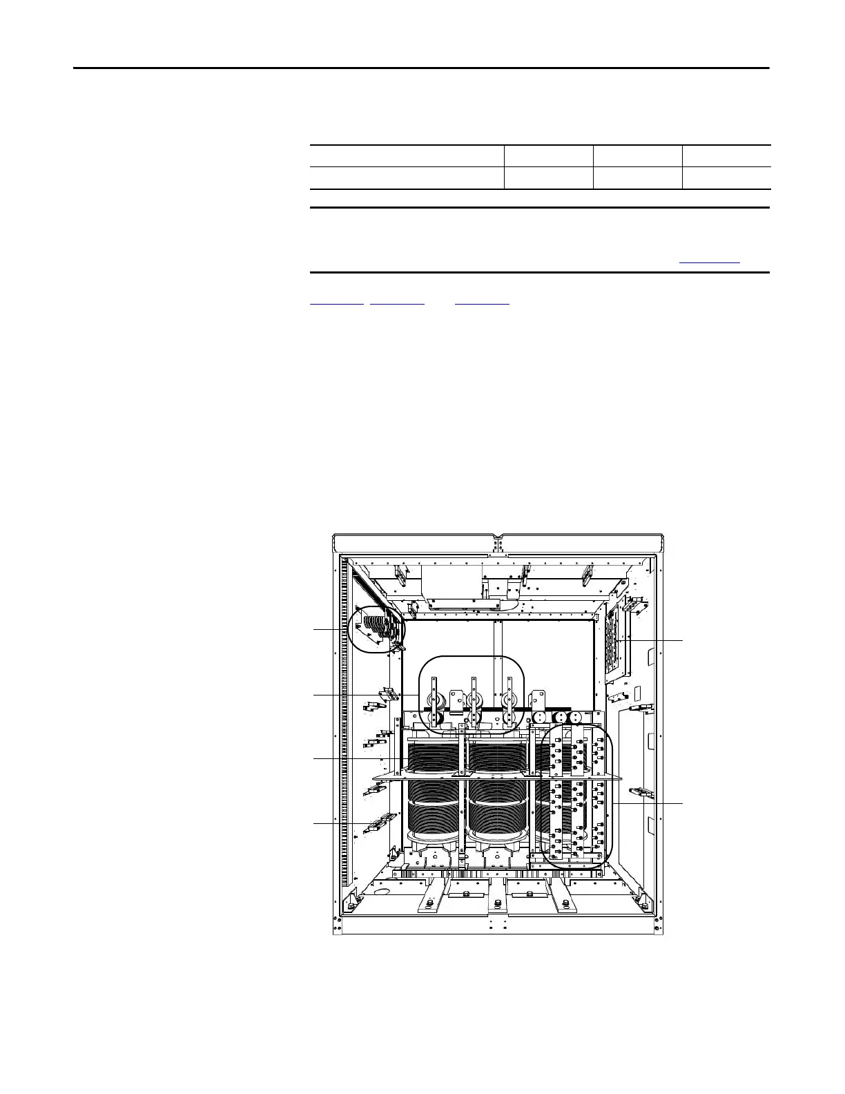
Figure 18 - Isolation Transformer Cabinet, Type A (Junction cabinet not applied)
Table 6 - Power Terminals
Incoming Line Cable Connections L1 L2 L3
Outgoing Motor Cable Connections U V W
If an optional cabinet is supplied, the incoming line and outgoing motor cable
connections are in the Bypass cabinet. Refer to the PowerFlex 6000 Medium
Voltage Variable Frequency Drive User Manual, publication 6000-UM002
.
Isolation transformer
Cable clamp
Voltage Sensing
Board
L1L2L3
U
V
W
Power cable
connections to
Power Modules
Incoming line power
cable connections
Outgoing motor power
cable connections

 Loading...


