Publication 2098-IN003E-EN-P — April 2004
Interconnect Diagrams B-7
Shunt Module Interconnect
Diagrams
This section contains the interconnect diagrams connecting the
Ultra3000 drives with active and passive shunt modules. Refer to
External Shunt Kits in Appendix C for Ultra3000/shunt combinations.
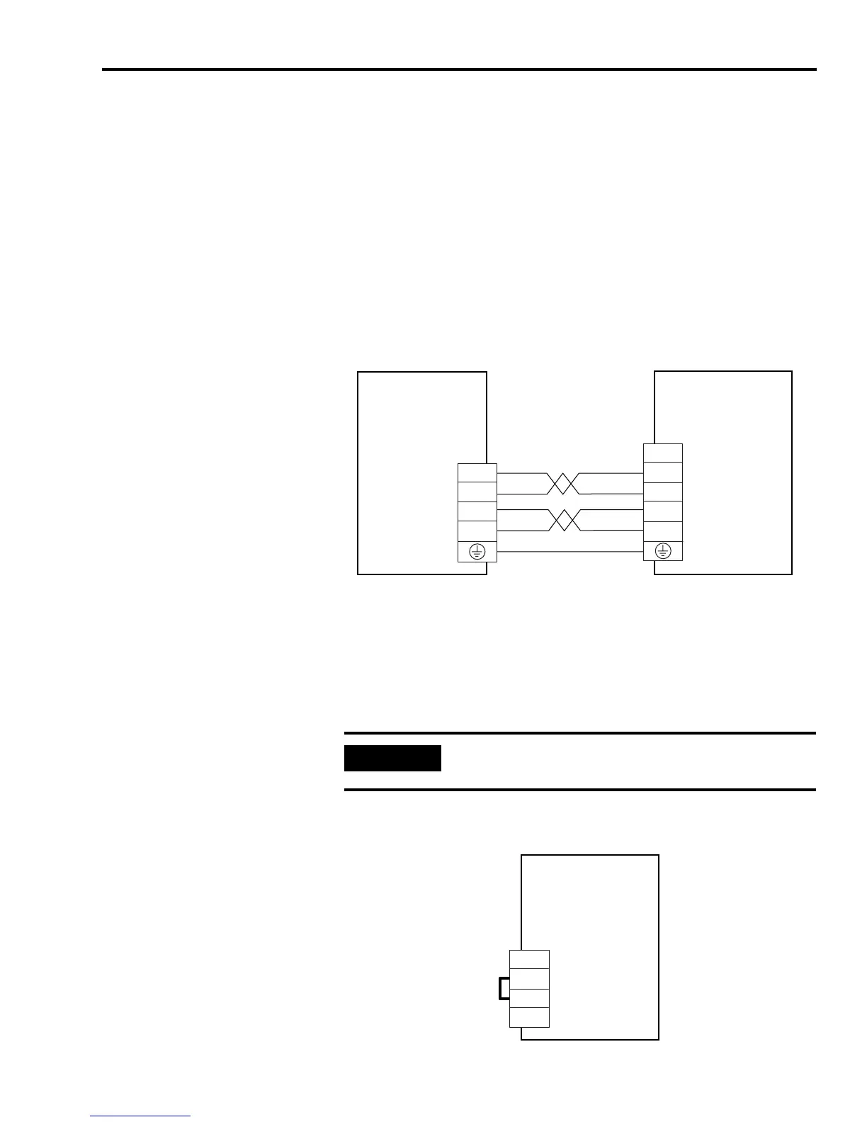
Active Shunt Module Diagrams
In the figure below, the Ultra3000 (2098-DSD-005x-xx, -010x-xx, or
-020x-xx) is shown wired with the 2090-UCSR-A300 active shunt
module.
Figure B.5
External Active Shunt Module Interconnect Diagram
Passive Shunt Module Diagrams
In the Figure B.6, the Ultra3000 is shown wired for internal shunt
operation. This is the factory default jumper setting.
Figure B.6
Internal Shunt Interconnect Diagram
TB1
DC+
DC-
L1
L2/N
DC+
DC-
L1
L2/N
Ultra3000
Digital Servo Drives
2098-DSD-005x-xx,
-010x-xx, and -020x-xx
External Active
Shunt Module
2090-UCSR-A300
DC Bus Connections
for Active Shunt Module
AC Input Power
Connections
IMPORTANT
Internal shunt operation is only present on the drives
listed in the figure below.
TB2
1
2
3
Ultra3000
Digital Servo Drives
2098-DSD-030x-xx,
-075x-xx, -150x-xx,
-HVxxx-xx, and
-HVxxxX-xx
Internal Passive Shunt
Resistor Connections

 Loading...


