Publication 2098-IN003E-EN-P — April 2004
2-28 Ultra3000 Connector Data
Using an External +5V Logic Supply
When using an external +5V dc power supply with your Ultra3000
(2098-DSD-005, -010, and -020), the +5V dc must not be grounded
inside the supply, since it will be referenced to the drive common.
External +5V dc power supply connections should be made to CN1-2
and CN1-3.
The following table provides a description of the requirements for an
external +5V dc power supply used to power the logic.
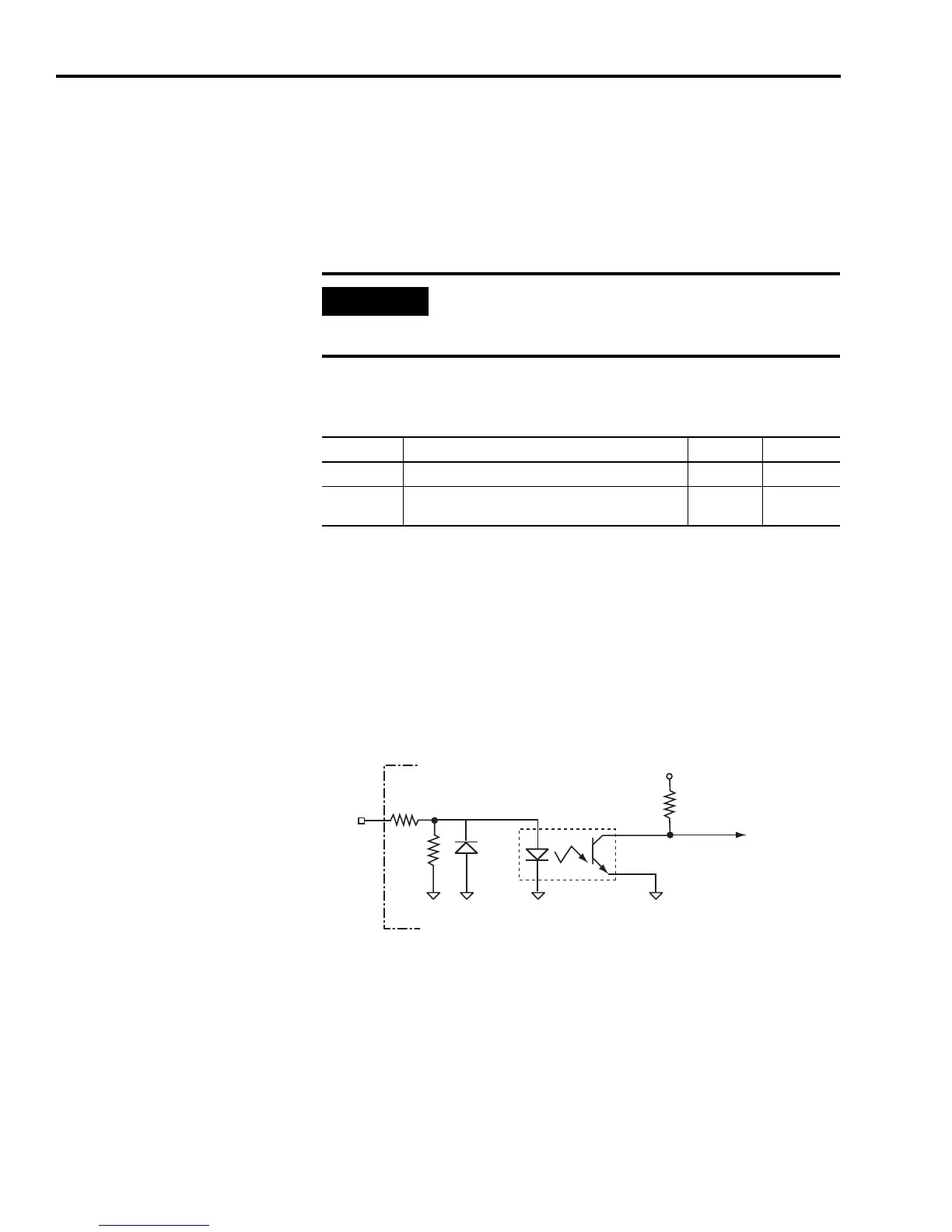
Digital Inputs
There are eight opto-isolated digital inputs. All digital inputs (SERCOS
and non-SERCOS) have the same configuration, as shown in the figure
below.
Figure 2.13
Digital Input Circuit
IMPORTANT
Using the drive-mounted breakout board with 24V to
5V auxiliary power converter is preferred to using an
external +5V dc power supply.
Parameter Description Minimum Maximum
Voltage Voltage tolerance of the external logic supply. 5.1V 5.25V
Current
Current output capability of the external +5V dc power
supply.
1.5A —
2.7k Ω
+5V
INPUTS
10k Ω
1k Ω
IOCOM
DGND
IOCOM
TLP121
tra
r
ve

 Loading...


