Publication 2098-IN003E-EN-P — April 2004
3-24 Connecting Your Ultra3000
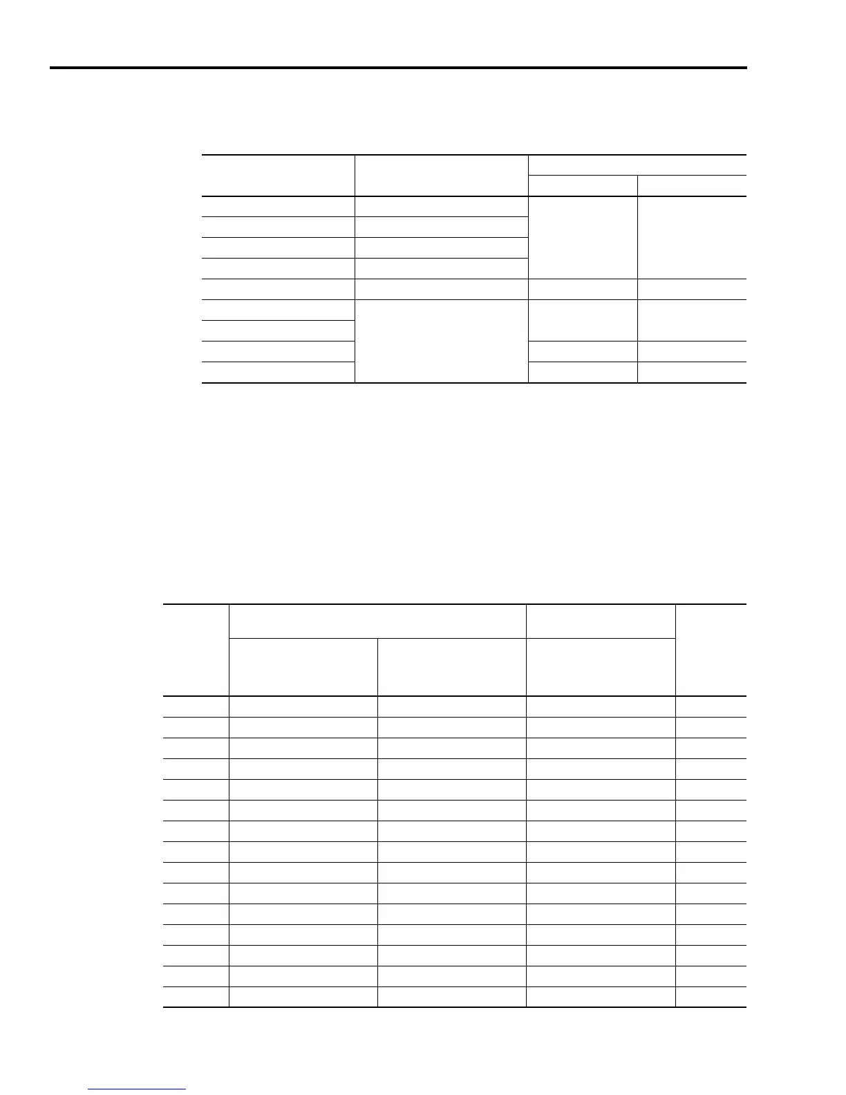
Refer to the table below for motor feedback cable catalog numbers
available for specific motor/feedback combinations.
1
Requires 2090-UXBB-DM15 drive-mounted breakout board, 2090-UXBK-D15xx breakout board kit, or
2090-UXCK-D15 mating connector kit.
Note: Refer to Maximum Feedback Cable Lengths on page A-13 to determine the maximum length of your motor
feedback cable.
Motor Feedback Connector Pin-outs
The following tables provide the signal descriptions and pin-outs for
the motor feedback (CN2) 15-pin connector to MP-Series (low inertia
and integrated gear), 1326AB, and N-Series motors.
For this Motor Series:
Using this Type of Motor
Feedback:
Use this Feedback Cable
Premolded: Flying Lead:
MPL-Axxxx or MPG-Axxx-xxx High-resolution encoder
2090-UXNFBMP-Sxx 2090-XXNFMP-Sxx
1
MPL-Axxxx Incremental encoder
MPL-Bxxxx or MPG-Bxxx-xxx High-resolution encoder
1326AB M2L/S2L High-resolution encoder
MPF-Axxxx or MPF-Bxxxx High-resolution encoder N/A 2090-XXNFMF-Sxx
1
F-Series
Incremental encoder
2090-UXNFBHF-Sxx 2090-XXNFHF-Sxx
1
H-Series
N-Series 2090-UXNFBN-Sxx 2090-XXNFN-Sxx
1
Y-Series 2090-UXNFBY-Sxx 2090-XXNFY-Sxx
1
Motor
Connector
Pin
High Resolution Feedback Signals for:
Incremental Encoder
Feedback Signals for:
Drive (CN2)
Connector
Pin
MPL-Bxxx-M/-S
MPL-A5xx-M/-S and
1326AB-Bxxx-M2L/-S2L
Motors
MPL-A3xx-M/-S
MPL-A4xx-M/-S
MPL-A45xx-M/-S
MPG-A/Bxxx-M/-S Motors
MPL-Axxx-H
MPL-Bxxx-H and
N-Series Motors
A Sine+ Sine+ AM+ 1
B Sine- Sine- AM- 2
C Cos+ Cos+ BM+ 3
D Cos- Cos- BM- 4
E Data+ Data+ IM+ 5
F Data- Data- IM- 10
K Reserved EPWR_5V EPWR_5V 14
L Reserved ECOM ECOM 6
N EPWR_9V Reserved Reserved 7
P ECOM Reserved Reserved 6
R TS+ TS+ TS+ 11
S TS- TS- TS- 6
T Reserved Reserved S1/Hall A 12
U Reserved Reserved S2/Hall B 13
V Reserved Reserved S3/Hall C 8

 Loading...


