Publication 2098-IN003E-EN-P — April 2004
Ultra3000 Connector Data 2-39
Analog Output
The Ultra3000 includes a single analog output (not supported on the
SERCOS models) that can be configured through software to represent
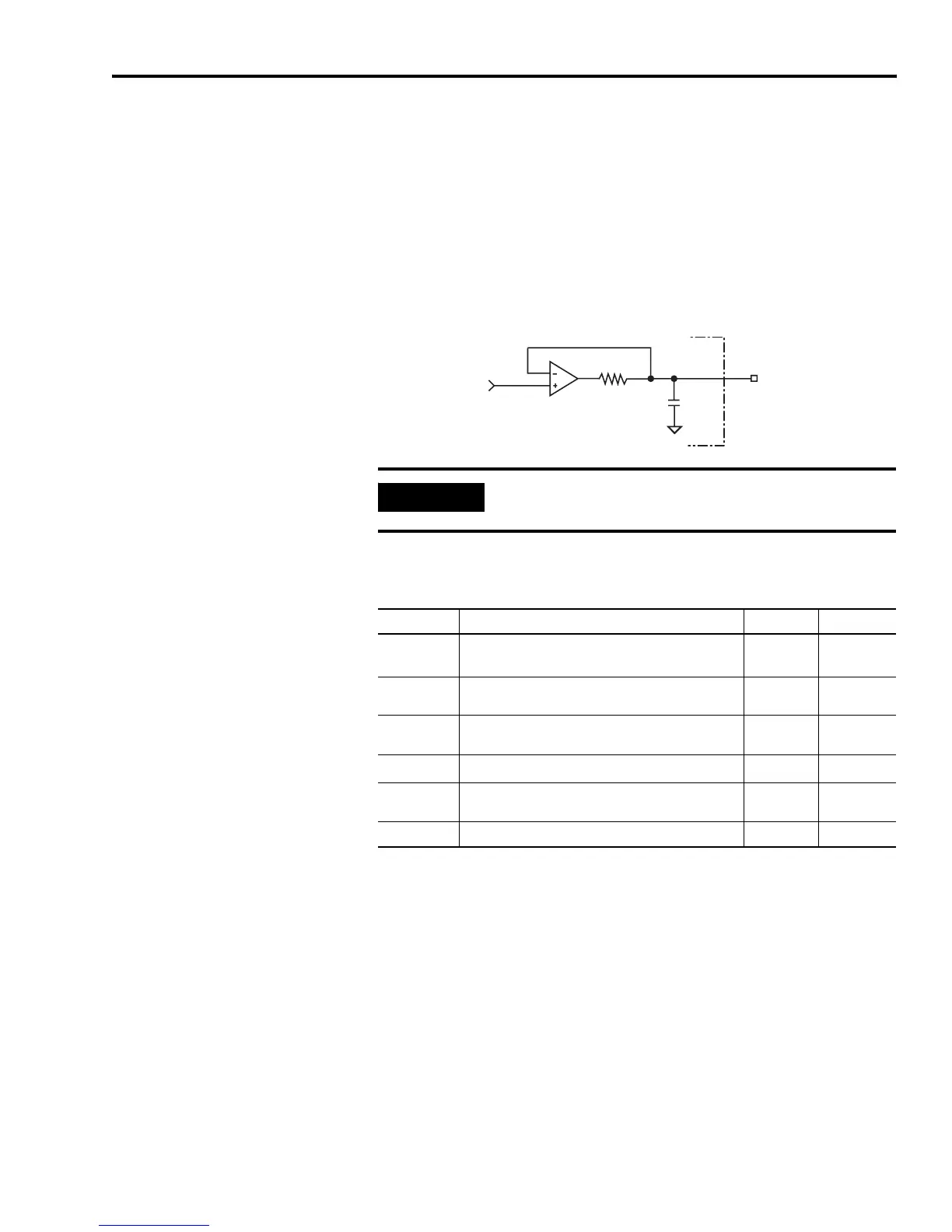
drive variables. Figure 2.36 shows the configuration of the analog
output.
Figure 2.36
Analog Output Configuration
The following table provides a description of the analog output
specifications.
1
The offset and gain errors of the analog output can be corrected for an application using Ultraware scale and
offset settings.
100 Ω
0.01
μ
F
AOUT
Ultra3000 Drive
IMPORTANT
Output values can vary during power-up until the
specified power supply voltage is reached.
Parameter Description Minimum Maximum
Resolution
Number of states that the output signal is divided
into, which is 2
(to the number of bits)
.
8 Bits —
Output
Current
Current capability of the output. -2 mA +2 mA
Output
Signal Range
Range of the output voltage. -10V +10V
Offset Error Deviation when the output should be at 0V. —
500 mV
1
Gain Error
Deviation of the transfer function from unity gain,
expressed in a percent of full scale.
—
10%
1
Bandwidth Frequency response of the analog output 50 Hz —

 Loading...


