Publication 2098-IN003E-EN-P — April 2004
Interconnect Diagrams B-23
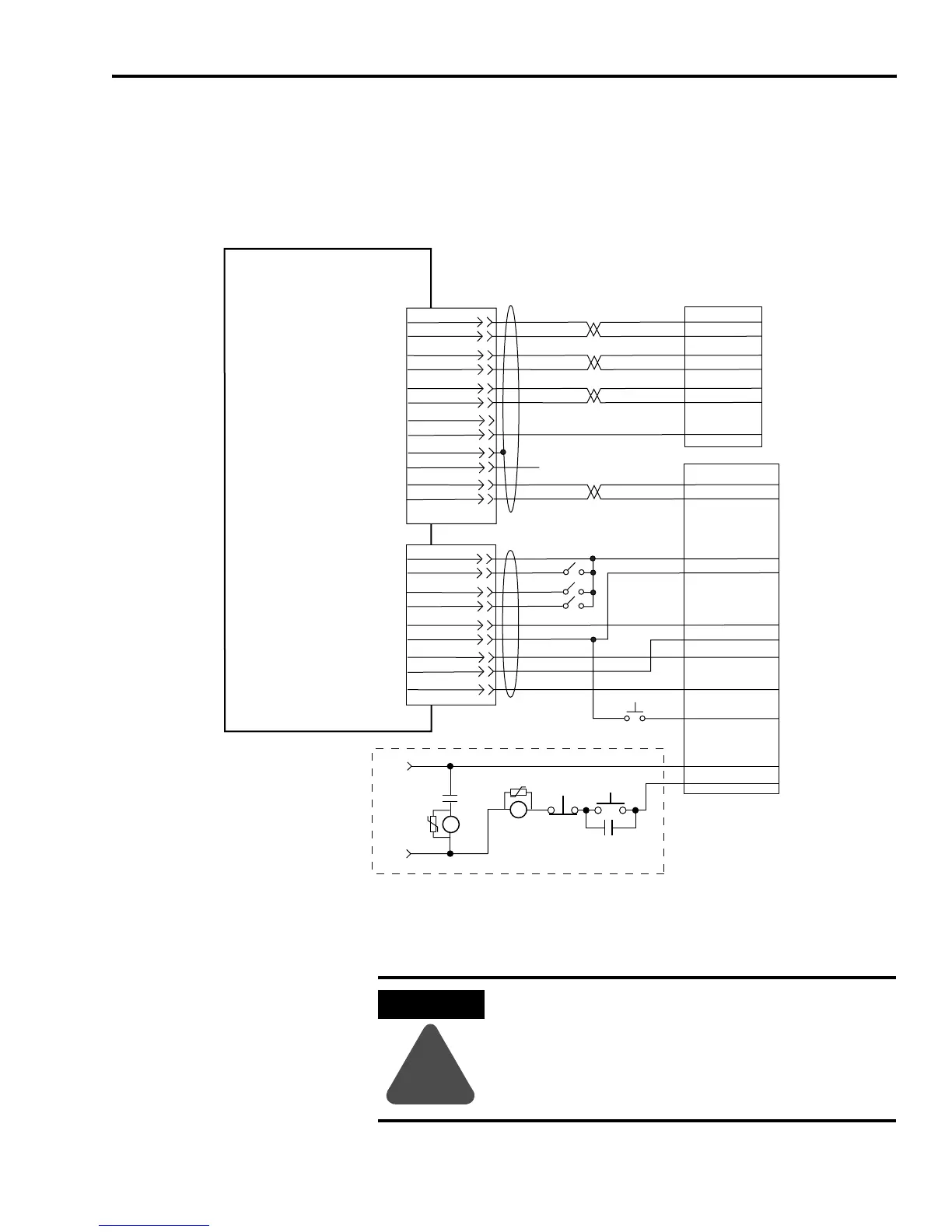
Ultra3000 to IMC-S
Compact Cable and
Interconnect Diagram
This section provides information to assist you in wiring the
IMC-S/23x-xx Compact Controller when connecting the 4100-CCS15F
feedback cable and 4100-CCA15F I/O cable to your Ultra3000.
Figure B.24
Ultra3000 to IMC-S/23x-xx Compact Controller Configuration
1
The preferred method for supplying the auxiliary +5V is by using the 12- or 44-pin drive mounted breakout board
with 24V to 5V auxiliary power converter (catalog number 2090-U3CBB-DM12 or -DM44). Auxiliary +5V power is
required to maintain encoder position with an external position controller during a controlled stop condition.
2
Drive Enable and Fault Reset are configured in Ultraware software.
3
Relay Output (CN1, pins 43 and 44) must be configured as Ready in Ultraware software.
A+
A-
B+
B-
Z+
Z-
+ENC (5V)
ENC COM
BLUE
BLACK
WHITE
BLACK
GREEN
BLACK
16
17
18
19
20
21
3
2
BLACK
1
7
4
10
5
11
6
12
3
9
8
2
IMC S Class Compact Controller
IMC-S/23
x-xx
Axis Servo and Feedback Connector
(located on bottom of controller)
Ultra3000
44-pin Breakout Board
(without SERCOS interface)
CN1 Connector
4100-CCS15F Feedback Cable
N/C
CMD+
CMD-
25
26
A+
A-
B+
B-
Z+
Z-
ENC PWR
ENC COM
REF+
REF-
SHIELD
STROBE
+24V I/O PWR
+24V I/O PWR
24V I/O COM
24V I/O COM
DIGITAL INPUT 1
DIGITAL OUT 1
DIGITAL INPUT 2
BLACK
BLUE
RED
WHITE
GREEN
BROWN
30
29
28
27
31
39
32
ORANGE
PURPLE
4
1
2
3
9
5
6
8
7
+ 24V
HOME
POS OT
NEG OT
24V COM
DRIVE EN
DRIVE EN
DRIVE FLT-
DRIVE FLT+
YELLOW
Fault Reset P.B.
2
2
RELAY OUT+
RELAY OUT-
43
44
Axis I/O Connector
(located on top of controller)
4100-CCA15F I/O Cable
3
3
1
24V AC/DC
or
120V AC,
50/60 HZ
START*
CR1*
M1*
CR1*
CR1*
STOP*
Refer to Attention statement below
ATTENTION
!
Implementation of safety circuits and risk assessment
is the responsibility of the machine builder. Please
reference international standards EN1050 and EN954
estimation and safety performance categories. For
more information refer to Understanding the
Machinery Directive (publication SHB-900).

 Loading...


