Publication 2098-IN003E-EN-P — April 2004
2-42 Ultra3000 Connector Data
Hall Inputs
The Ultra3000 can use Hall signals to initialize the commutation angle
for sinusoidal commutation. Hall signals must be single-ended and
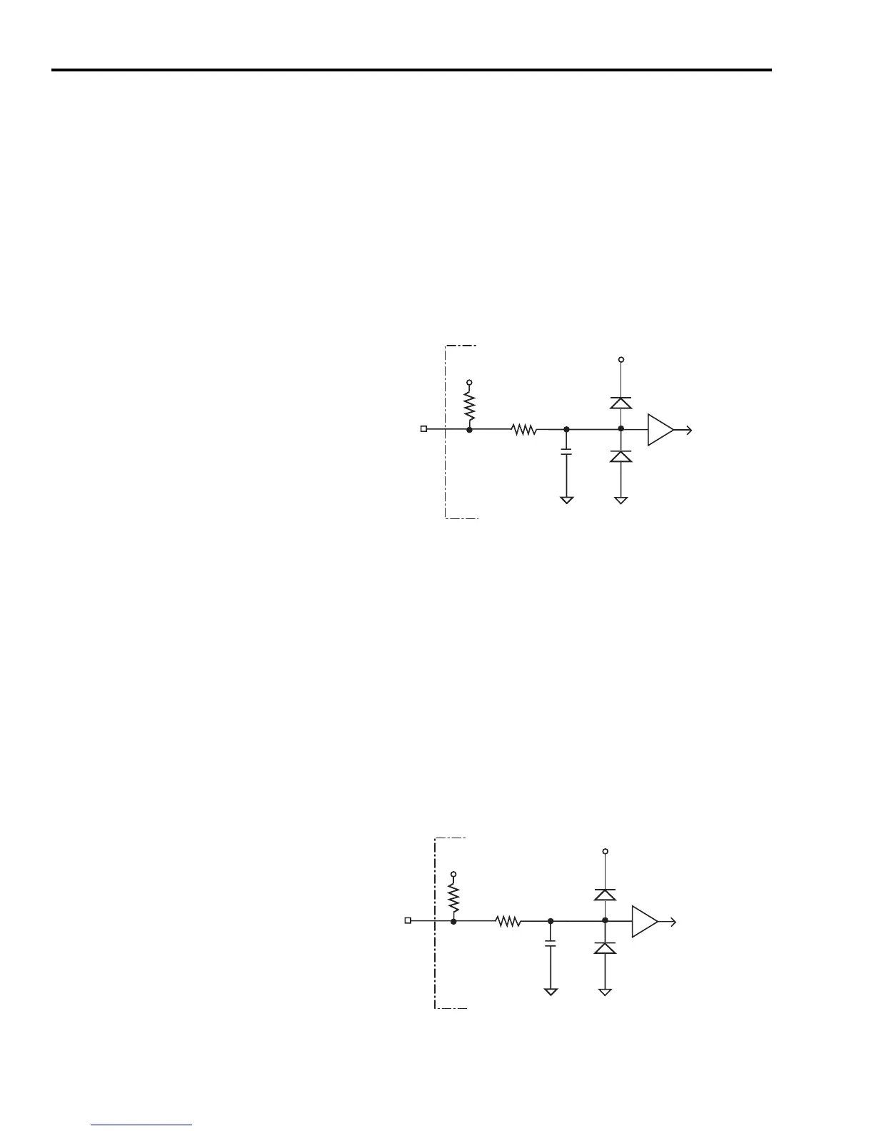
can be either open collector type or TTL type. Figure 2.38 shows the
configuration of the Hall inputs. If the motor does not have Hall
signals, the drive can be configured through software to ignore the
signals.
Figure 2.38
Hall Input Configuration
Thermostat Input
The Ultra3000 can monitor a thermostat signal from a motor and will
generate a fault if the motor overheats. Figure 2.39 shows the
configuration of the thermostat input. Figure 2.40 on page 2-43 shows
a typical connection to a motor with a normally closed thermostat.
The logic is designed so that an open condition will generate a fault. If
the motor does not have a thermostat signal, the drive can be
configured through software to ignore the signal.
Figure 2.39
Thermostat Input Configuration
1k Ω
1k Ω
+ 5 V
+ 5 V
56
μ
F
COMMON COMMON
S1, S2, or S3
Ultra3000 Drive
6.8k Ω
1k Ω
+ 5 V
+ 5 V
0.01
μ
F
COMMON COMMON
TS
Ultra3000 Drive

 Loading...


