Publication 2098-IN003E-EN-P — April 2004
B-18 Interconnect Diagrams
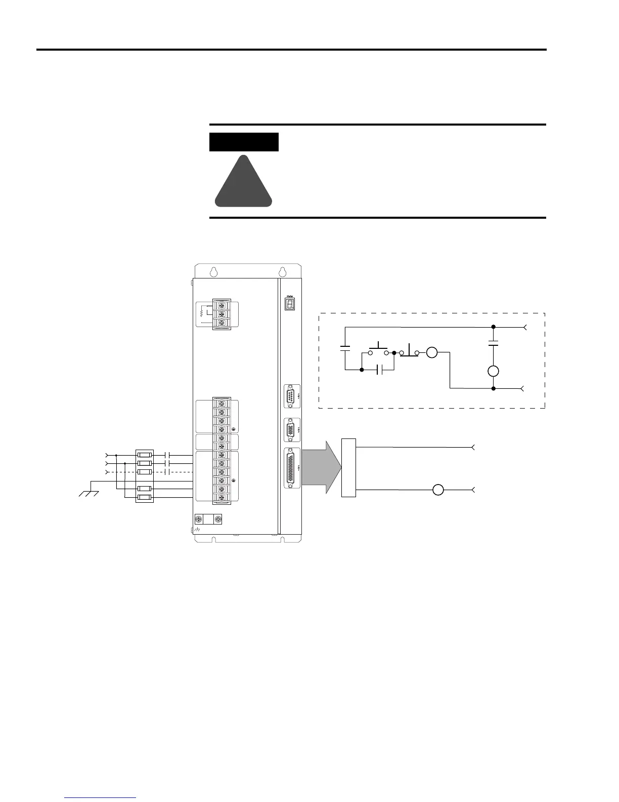
The 120V ac control string wired to the Ultra3000 (2098-DSD-075x-xx,
-150x-xx, -HVxxx-xx, and -HVxxxX-xx) drives is shown in the figure
below.
Figure B.18
120V ac Three-Phase Control String Example
ATTENTION
!
Implementation of safety circuits and risk assessment
is the responsibility of the machine builder. Please
reference international standards EN1050 and EN954
estimation and safety performance categories. For
more information refer to Understanding the
Machinery Directive (publication SHB-900).
CN1
Ultra3000
Three-Phase
AC Line
50/60 Hz
M1
U
V
W
+
-
L1
L2
L3
L1
AUX
L2/N
AUX
Motor
DC Bus
100-240 VAC
50/60 Hz
Internal
External
Shunt
1
2
3
TB2
TB1
Fuse
Block
L1
L2
L3
L1 Aux
L2/N Aux
120V AC
50/60 Hz
STOP
START
CR1
CR1
CR1
M1
Refer to Attention statement above
CR2
N.O. Relay Output+
N.O. Relay Output-
43
44
CR2
24V DC
Ultra3000
Note 20

 Loading...


