TROUBLESHOOTING
Ve ctor F® Se ries ▪ S ervice Ma nual ▪ M N- 46 89 5 ▪ R ev 1 ▪ 7/ 20
92
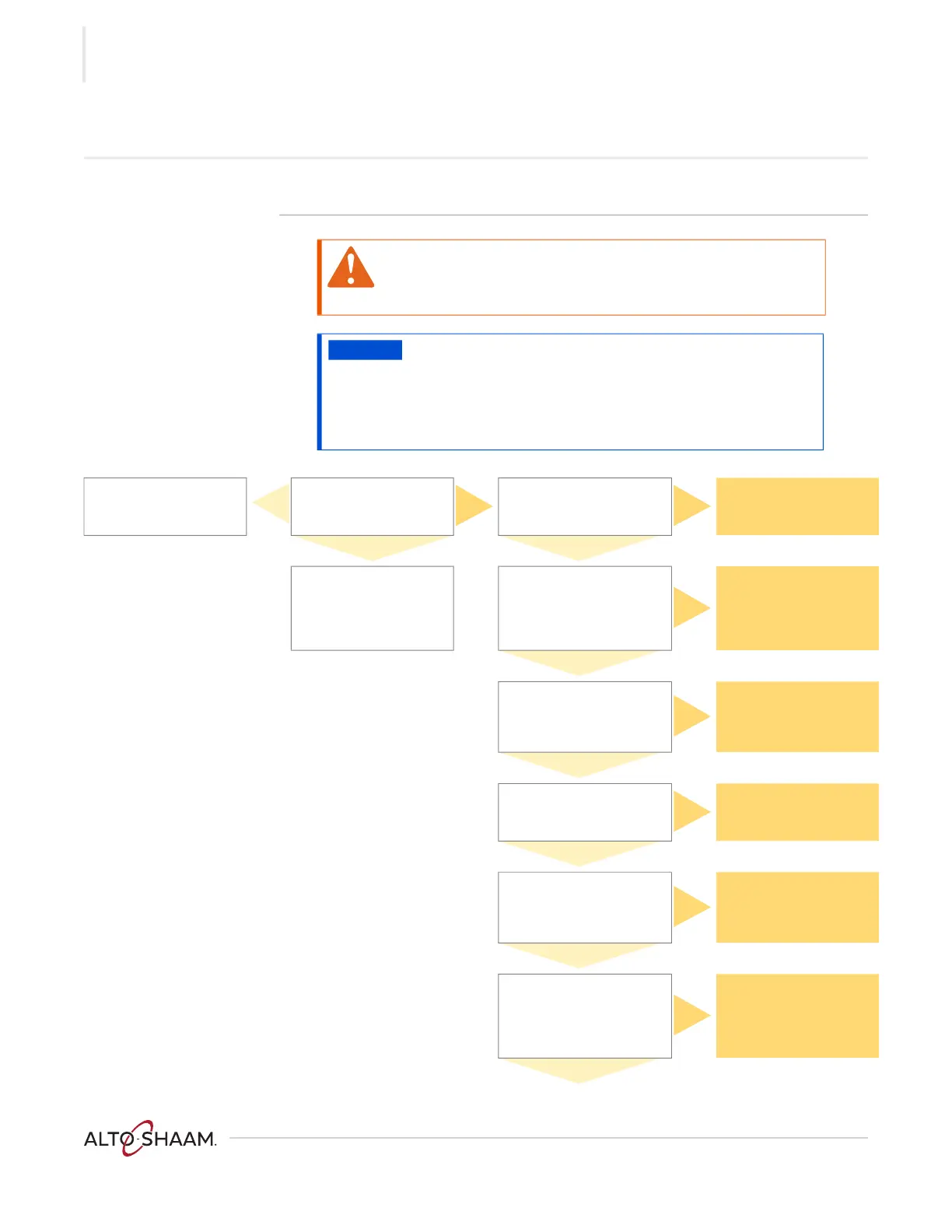
The Check Fan Indicator Light is Illuminated
Before you start Put the oven into a heating mode.
WARNING: Electric shock and arc flash hazard.
Use caution when measuring line voltage.
Wear Personal Protective Equipment (PPE).
NOTICE
Do not operate the oven in a cooking mode for an extended
period of time with the service panels removed. Damage to the
electronics may occur without adequate cooling airflow.
An auxiliary fan must be used if the oven will be operated in a
cooking mode for an extended period of time with the service
panels removed.
Inspect the cooling fan
filters. Clean and replace
as required.
Yes
The indicator light is
controlled by a 130°F
thermal switch(es). Are
the cooling fans running?
No
Test the operation of the
thermal switch(es)? Do the
contacts open at 110°F or
lower?
No
Replace the thermal
switch.
Yes Yes
Inspect the electronics
compartment near the
thermal switch(es) for an
abnormal heat source.
Repair or replace as
required.
Is LED2 on the control
board illuminated?
No
Replace the control board.
Yes
Measure the DC voltage
across terminals 2 and 3 of
the P 21 connector on the
control board. Is the voltage
12VDC?
No
Replace the control board.
Yes
Measure the DC voltage
across terminals + and - of
the RL 1 relay. Is the voltage
12VDC?
No
Repair or replace the
wires from P 21 connector
on the control board to
the RL 1 relay.
Yes
Measure AC voltage across
TB 16 and TB 22. Does the
voltage correspond to the
voltage printed on the serial
number tag?
No
Reset the circuit breaker.
Repair or replace the
wires to TB 16 or TB 22.
CE units— Repair or
replace the line filter.
Yes
Measure AC voltage across
the common terminal at the
RL 1 relay and TB 16. Does
the voltage correspond to
the voltage printed on the
serial number tag?
No
Repair or replace the
wires from TB 22 to RL 1
relay.
Yes
 Loading...