Installation
36
10" Modero Touch Panels
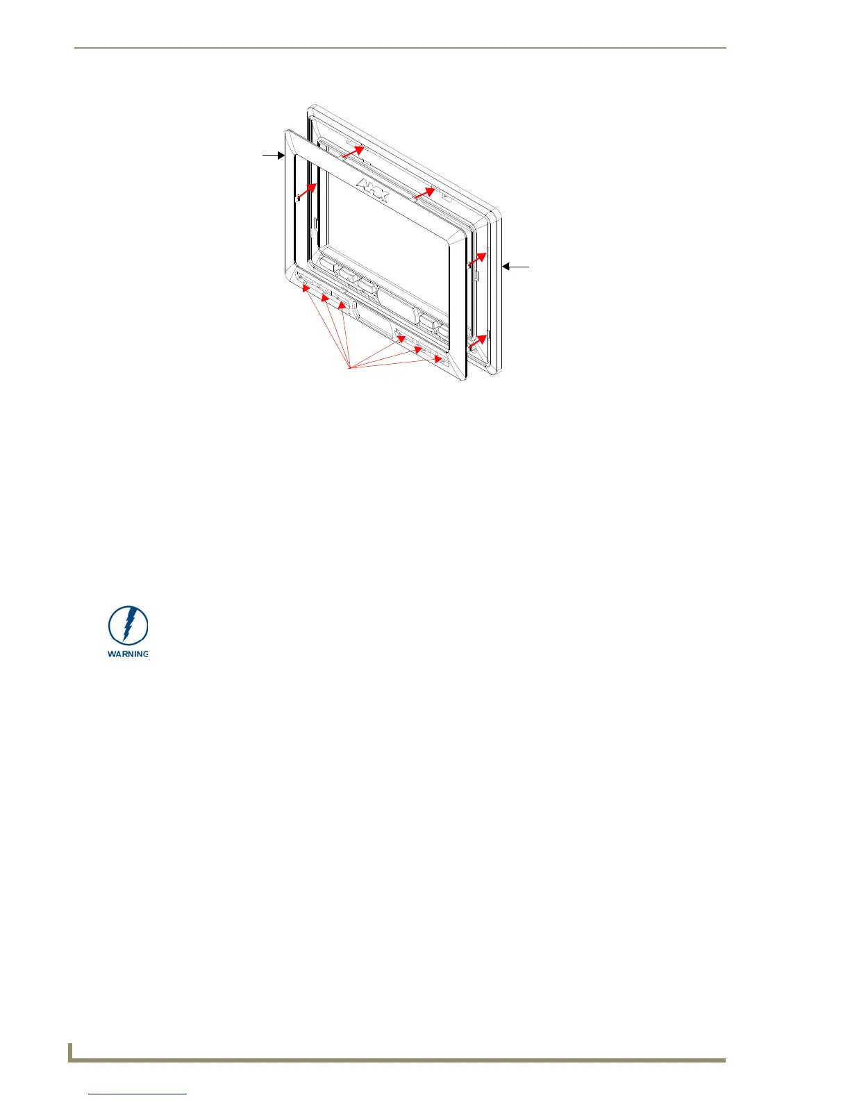
9. Firmly press down around the Button Trim Ring until all of the latches are securely inserted into their
openings on the Faceplate, and the Button Trim Ring is securely fastened. Verify the Button Trim Ring is
firmly inserted onto the Faceplate and that there are no gaps between this Trim Ring and the outer surface
of the Faceplate.
10. Place the Faceplate back onto the main NXD-CV10 unit. Make sure to align the Microphone, Light, and
PIR Motion sensor locations on the main unit to their respective openings on the Faceplate assembly.
Pre-Wall Installation of the Conduit Box
Wall Mount panels (NXDs) are contained within an outer housing (back box). This back box is not removed
when installing the NXD into a Conduit Box (CB-TP10). The back box is only removed to gain access for the
replacement of the internal components.
The CB-TP10 is an optional metallic box that is secured onto a stud/beam in a pre-wall setting (where no
walls are present). Installation procedures and configurations can vary depending on the installation
environment. This section describes the installation procedures for the most common installation scenario. The
most important thing to remember when mounting this conduit box is that the NXD-CV10 Mounting Tabs
must lie flush against the outside of the sheetrock (FIG. 38).
Refer to SP-2259-02 for detailed installation dimensions.
It is recommended that you cut out the surface slightly smaller than what is outlined in the
installation drawings so that you can make any necessary cutout adjustments.
The wiring knockouts on the left side will be used for the NXD-CV10 Wall Mount panel
connectors, so always secure the conduit box to the stud using the Stud Mounting Holes on the
right side of the box.
1. Rest the right Stud Mounting tabs onto the stud (keeping the knockouts on the left). Be sure to leave
enough of a gap between the stud and NXD Mounting tabs to accommodate the installation of the
drywall or sheetrock after the conduit box has been mounted. Ultimately, the Mounting Tabs
should lie flush against the outside of the sheetrock.
2. Fasten the CB-TP10 conduit box to the stud through the holes on the right Stud Mounting tabs (FIG. 38),
using either nails or screws.
FIG. 37 Inserting the Button Trim RIng
Button openings
Button Trim Ring
Faceplate (outer surface shown)
INSTALLER: LEAVE A GAP BETWEEN THE STUD AND CONDUIT BOX
MOUNTING TABS TO ACCOMMODATE THE DRYWALL or SHEETROCK.
This gap allows the installation of the drywall or sheetrock after the CB-TP10 Conduit
Box has been installed.

 Loading...