Installation
37
10" Modero Touch Panels
3. Remove the wiring knockouts from the left side of the conduit box (CB-TP10) (FIG. 38) to accommodate
the cables being threaded through to the NXD touch panel.
4. Thread the incoming power, RJ-45 audio/video, Ethernet, and USB wiring through the knockouts (use of
the left wiring knockouts are recommended with this installation).
Leave enough slack in the wiring to accommodate any re-positioning of the panel.
5. Install the drywall/sheetrock before inserting the main NXD unit into the CB-TP10.
Installation of an NXD Touch Panel
The NXD-CV10 can be installed either directly into the (optional) CB-TP10 or other solid surface
environment using the two different mounting options: drywall clips or solid surface screws. The following
sections describe mounting the touch panel directly into a pre-wall conduit box, a solid surface or drywall, and
optional NXA-RK10 Rack Mount Kit for installation.
Installing the NXD panel within a Conduit Box
The conduit box must be mounted prior to continuing this section. Refer to the procedures in the
Pre-Wall Installation of the Conduit Box section on page 36 for detailed pre-wall installation instructions.
Verify that all necessary cables have been threaded through the knockouts on the left of the conduit box and the
connections have been tested prior to installation of the NXD-CV10.
1. Remove the Faceplate/bezel (A in FIG. 39) from the main NXD unit (B in FIG. 39) by gripping the
faceplate and pulling with gentle outward force.
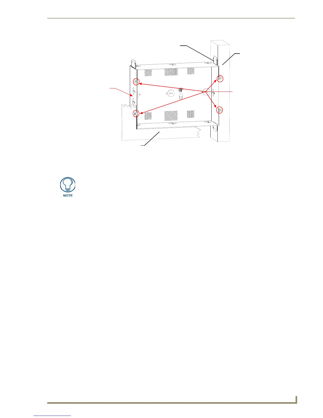
FIG. 38 CB-TP10 conduit box components
Stud
Stud Mounting tabs
Drywall or sheetrock
Wiring
knockouts
(must be
located on
left side)
NXD Mounting tabs
(should lie flush against
the outside of the wall)
Remember that when mounting this conduit box, the NXD mounting tabs must lie
flush against the outside of the sheetrock.

 Loading...