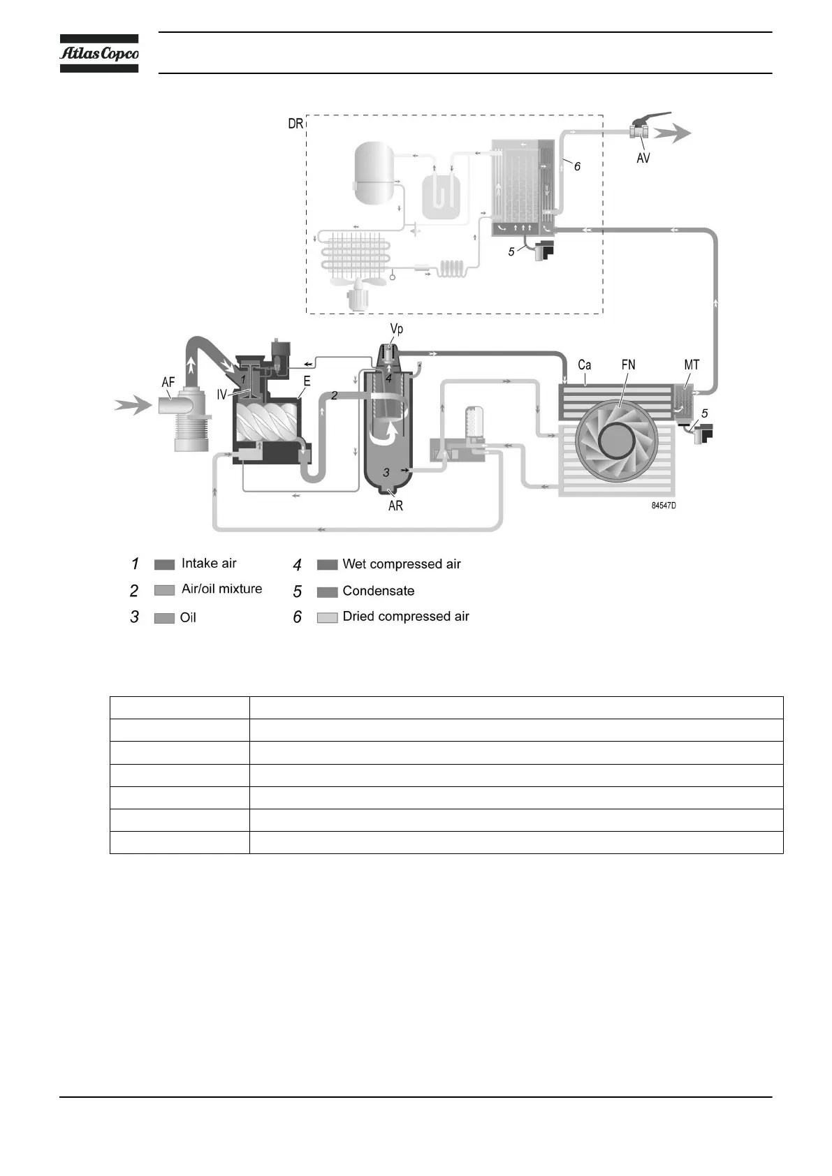
Flow diagram, air circuit (compressors with integrated dryer)
Reference Description
1 Intake air
2 Air/oil mixture
3 Oil
4 Wet compressed air
5 Condensate
6 Dried compressed air
Description
Air drawn through inlet filter (AF) and open inlet valve (IV) of the unloader is compressed in compressor
element (E). A mixture of compressed air and oil flows into the air receiver/oil separator tank (AR). The air
is discharged through outlet valve (AV) via minimum pressure valve (Vp) and air cooler (Ca).
The air cooler is provided with a moisture trap (MT).
On compressors with integrated dryer, the air flows through air dryer (DR) before it is discharged through
outlet valve (AV). Also see section Air dryer.
Under all circumstances, the minimum pressure valve (Vp) keeps the pressure in the separator tank (AR)
above the minimum value that is required for lubrication of the compressor element. An integrated check
Instruction book
18 2920 7180 30
 Loading...