Function
• To display the actual value of the measured data (analog inputs) and the status of the digital inputs
(e.g. emergency stop contact, motor overload relay, etc.).
• To select the digital input to be shown on the chart in the main screen.
Procedure
Starting from the main screen,
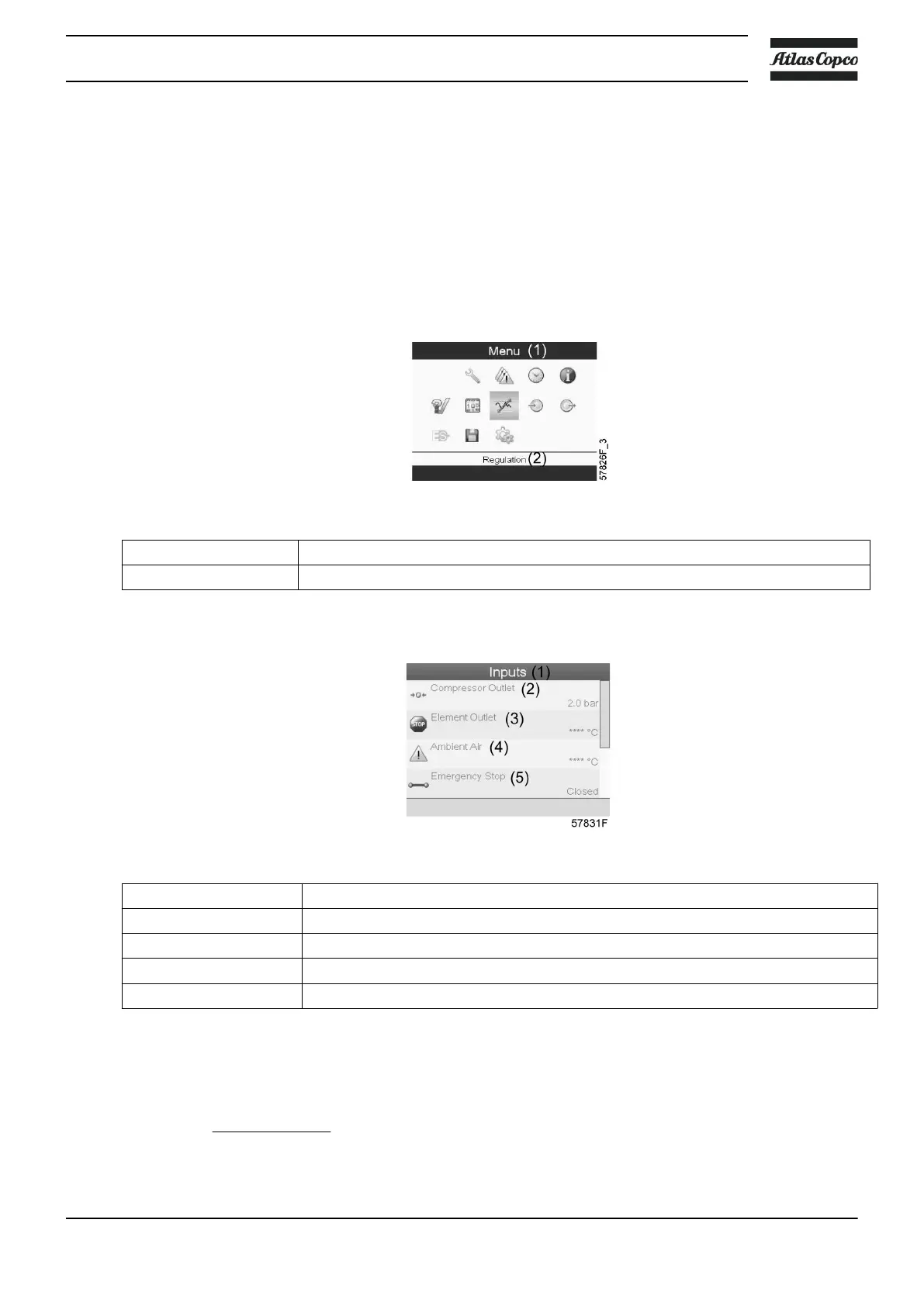
• Move the cursor to the action button Menu and press the Enter key. Following screen appears:
Text on image
(1)
Menu
(2)
Regulation
• Using the Scroll keys, move the cursor to the Inputs icon (see above, section Menu icon).
• Press the Enter key. A screen similar to the one below appears:
Text on image
(1)
Inputs
(2)
Compressor Outlet
(3)
Element Outlet
(4)
Ambient Air
(5)
Emergency Stop
• The screen shows a list of all inputs with their corresponding icons and readings.
• If an input is in warning or shutdown, the original icon is replaced by the warning or shutdown icon
respectively (i.c. the Stop icon and the Warning icon in the screen shown above).
A small chart icon, shown below an item in the list means this input signal is shown on the chart at the
main screen.
Any analog input can be selected.
Instruction book
2920 7180 30 81
 Loading...