V
vlopezAug 18, 2025
Why is my Baxi EcoBlue Advance Heat 19 Boiler flashing 1 red light indicating a sensor error?
- GgonzalezmichaelAug 18, 2025
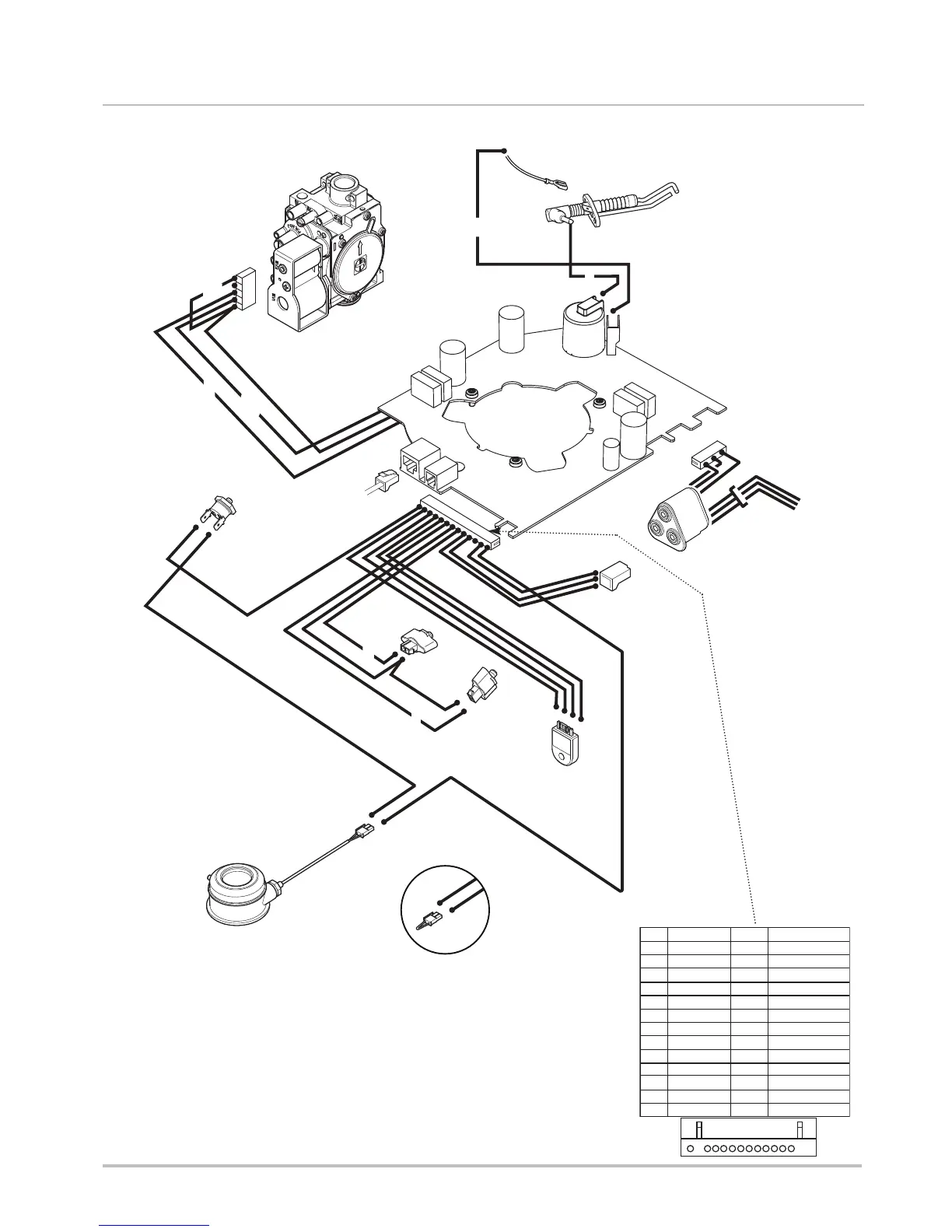
If your Baxi Boiler displays 1 red flash, it indicates a sensor error. This could be due to a bad connection to the flow or return temperature sensor, a fault with the temperature sensors, low or no flow through the boiler, or reverse flow through the boiler. To address this: * Check the connections to the temperature sensors/PCB and the condition of the wiring loom. * Check the resistance of the temperature sensors. * Check the pump operation and system circulation.