WARNING
When changing components ensure that both the
gas and electrical supplies to the boiler are isolated
before any work is started.
Use the “Socket & See” electrical test point
to confirm safe isolation.
When a component has been changed recommission
the boiler as described in Section 7.
Always examine any seals or gaskets, replacing
where necessary. Where a seal or gasket is supplied
with a spare part it should be used, irrespective of
the condition of the original.
The Case Front Panel MUST seal effectively against
the air box side panels.
50 EcoBlue Heat 7219717 - 02 (08/15)
10 Maintence
10.3 Specific Maintenance Operation
1. See section 10.2 for removal of lower front panel and front
panel.
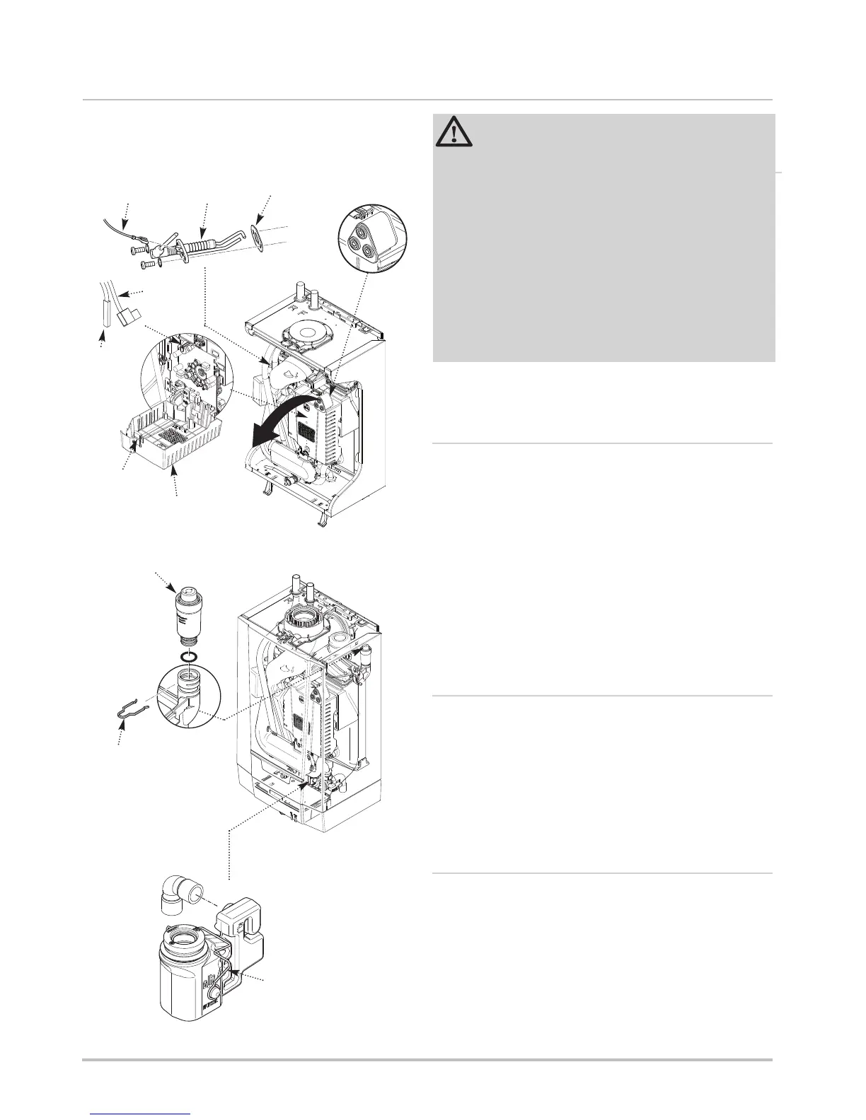
10.3.1 Spark Ignition Electrode (Fig. 39)
1. Disengage the fan protective cover securing tab and lower
the cover.
2. Disconnect the ignition electrode plug from the PCB and the
earth wire from the electrode.
3. Undo the two securing screws securing and remove the
electrode and gasket.
4. Fit the new electrode and if necessary replace the gasket.
Connect the electrode lead to the PCB and earth wire to the
new electrode.
10.3.2 Automatic Air Vent (Fig. 40)
1. Remove the clip securing the automatic air vent.
2. Manoeuvre the air vent out of the adaptor in the heat
exchanger.
3. Fit the new air vent and if necessary replace the ‘O’ ring .
Refit the securing clip.
10.3.3 Condensate Trap (Fig. 41)
1. Disengage the condensate trap retaining clip and disconnect
the condensate drain. Carefully pull out the trap.
2. Thoroughly clean the trap and if necessary replace the seal.
3. Fill the condensate trap with tap water to a depth of
approximately 75mm.
4. Carefully relocate the condensate trap in the boiler ensuring
all seals are located properly and reattach the retaining clip.
Gasket
Spark Ignition
Electrode
Earth
Wire
Automatic
Air Vent
Condensate Trap
Press the tap to
hinge down the
Fan Protective
Cover
Fan Protective
Cover
Tab
Clip
Earth Wire
Ignition
Electrode
Plug
Push the Condensate Trap
Clip either side to release
the trap
Fig. 39
Fig. 40
Fig. 41
“Socket & See”
Electrical Test Point
 Loading...