EasyManuals Logo
Home>Bay-Tek>Arcade Game Machines>AXE MASTER

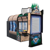
Bay-Tek AXE MASTER User Manual

Bay-Tek AXE MASTER
82 pages
To Next Page IconTo Next Page
To Previous Page IconTo Previous Page
Page #41 background imageLoading...
Page #41 background image
41
AACB9605-CBL
I/O Aux Board
A5CORD13000
USB communication
to motherboard
Red and Yellow
Communication
LEDs ON
Green
Power
LED
Flashing
Right Side
Board Address
Dips #1 ON
Dip #2 OFF
WIRING DIAGRAM
Low Ticket Switch
Wired Normally Open
AASW200
1/4” Spacer A5SENY020
AACE29023
To 12 Volt DC Bill Acceptor
A5AC9101 or A5AC9094
AACE29014
AACE29034
Power in from
Power Dist Bd
Ticket
Counter
AACO1000
AACE29013
Game
Counter
Coin Switches
and Lights
AACBL4A-DOORA
AACE29023
4-5 VDC normally
on switches.
Goes to 0 when
activated.
Blue & Black Wires: 5 VDC when notch opto
is blacked. 0 VDC when sees a notch.
White & Black Wires: 5 VDC when enabled
and tickets are trying to dispense.
AACE29023
AACE29023
To Ticket
Dispenser
Part # A5TD1
Notch Signal
Com Ground
Enable Signal
12 Volt Power
AACE29023
RIGHT SIDE
Clicks as tickets are
being dispensed.
Clicks as you choose
your game mode.

Questions and Answers:

Question and Answer IconNeed help?

Do you have a question about the Bay-Tek AXE MASTER and is the answer not in the manual?

Bay-Tek AXE MASTER Specifications

General IconGeneral
BrandBay-Tek
ModelAXE MASTER
CategoryArcade Game Machines
LanguageEnglish

Related product manuals