65
CHAPTER 4: Full Configuration
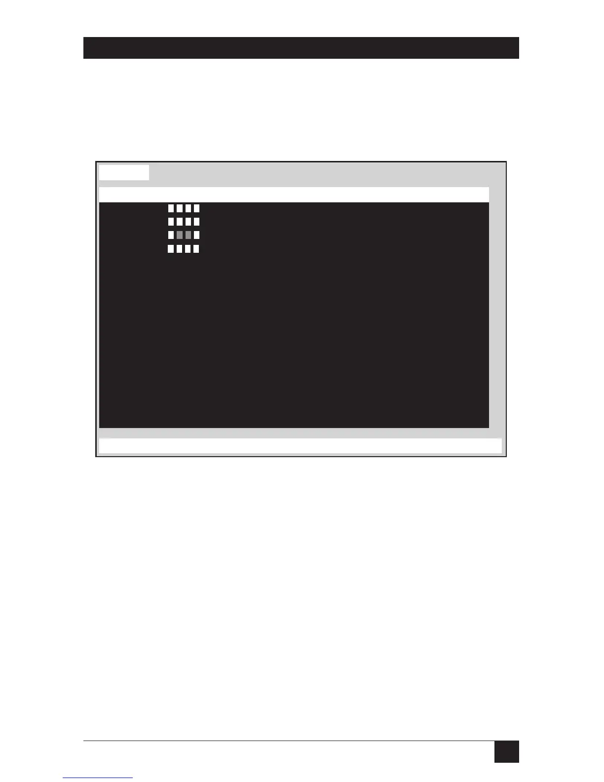
4.8 The Status Page
This page displays status information for each port board (set of four CPU ports)
in the Matrix ServSwitch system. This information is an invaluable tool when
expansion or reconfiguration is necessary.
Figure 4-9. The Status page.
These are the status-information fields:
Computers
Indicates the numbers of the CPU ports on each port board.
Power
Green squares indicate that the corresponding CPUs attached to the port board
are powered up. The CPUs are shown from left to right, in the order of their CPU
ports (from lowest-numbered to highest-numbered).
Slot
Displays the unit-level numbers of the port boards, listed in the order of their slots
in the Switch’s backplane, from 1 (the bottom board) through 4 (the top board).
Status
Name of keyboard-video-mouse station (KVM), up to 16 characters
Computers Power Slot Ver KVM CPU User Status
1-4 1 16H PC 14 Bob View mode
5-8 2 16H PC 5 David Share mode
9-12 3 16H PC 14 Sharon View mode
12-16 4 16H PC 1 Bob Share mode
17-20 No response
21-24 No response
25-28 No response
29-32 No response
33-36 No response
37-40 No response
41-44 No response
45-48 No response
49-52 No response
53-56 No response
57-60 No response
61-64 No response
 Loading...