Electricalconnection
322000010S|V1B|07/2017
18
©byBlum‐Novotest
5. Electricalconnection
NOTICE
Damageandmalfunctionofthemeasuringsystemispossiblecausedbyfaultycablemount‐
ing
Connectordisconnectconnectingcablesorplugconnectionswithoutpowersupplyonly.
Observefail‐safecablelayingaccordingtotheregulationsformeasuringsystemcable s.
Connectthecableshieldingonthecontrolsidewiththemachineearth.Atadapterconnec‐
tionstheshieldingmustbedirectedovertheplughousingandthecompleteplugconnec‐
tionmustbemountedisolated.
Observeintactnessofgasketandadjustinggrooveofplugconnector.
Tightentheplugconnectorfirmly(M
d
= 2.0 ... 2.5 Nm).
NOTICE
Damagetothemeasuringsystembyshortcircuitpossible.
Theoutputscannotbeconnectedinparallel!
Connecteachindividualwiretoitsownterminal.
NOTICE
Damagesofthemeasuringsystembychipsarepossible.
Neverinstallcablesandwireswithoutprotectionintheworkingarea.
Protectcablesandwiresintheworkingareaagainstflyingchips,e.g.byprotectionhose,
protectionspring,cover,etc.
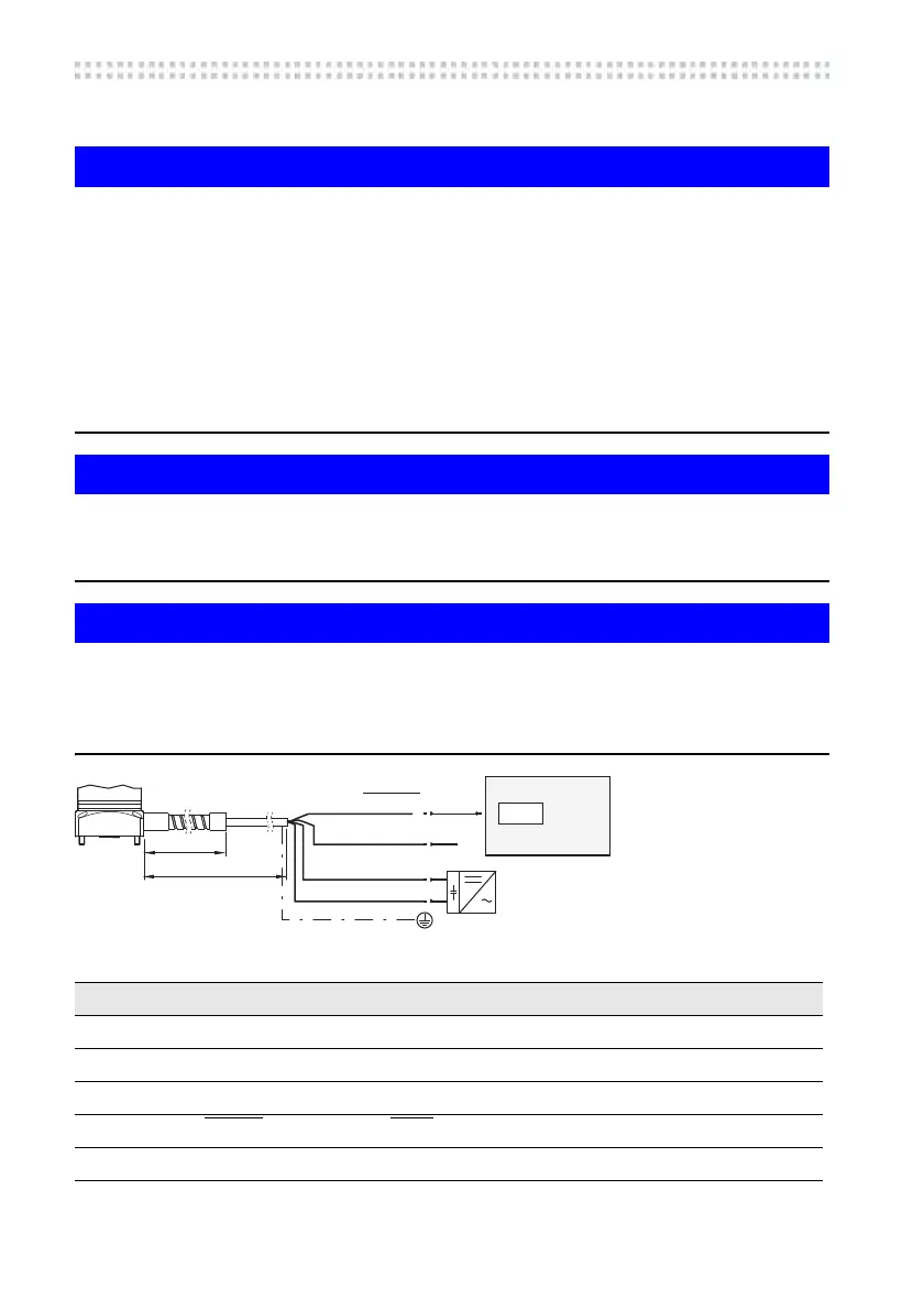
Fig.5‐1
Tab.5‐1
CNC
24V
0V
x.xx
YE STATUS
BN
1,5m
10m
WH
GY STATUS
Colour/Pin Connection Designation Data
white GND Ground 0V
brown U
B
Powersupply 12 ... 30 V (stabilized) / 100 mA
yellow STATUS Outputstatic 12 ... 30 V / 50 mA
grey STATUS
Outputstatic 12 ... 30 V / 50 mA
Housing ‐‐‐ Shielding
 Loading...