Robert Bosch GmbH
en 17
ACS 500
1 689 975 197 (2006-09-22)
9.3 Control/display unit
9.3.1 Replacing control/display unit
Procedure:
1. Turn off ACS 500 at master switch.
2. Remove mains connector.
3. Remove electronic compartment cover.
45
9
79
0
-2
1,2
1,2
3
4
8
7
10
11
9
5
6
12
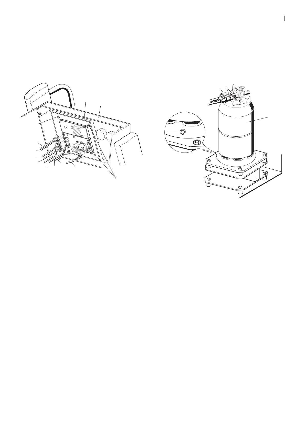
Fig. 12: Control/display unit
4. Connect connecting leads (3 to 10) on the rear of the
control/display unit (11).
5. Remove hexagon nuts (1) and washers (2).
6. Lift control/display unit out of control panel (11).
7. Install new control/display unit in control panel (11).
8. Secure control/display unit with hexagon nuts (1) and
washers (2).
9. Connect connecting leads (3 to 10) control /display unit
(see Section 12.1).
The following additional actions must be performed after
the replacement:
Select national language.
Set date and time.
Enter workshop address.
Calibrate force sensors (see section 6.1).
Calibrate pressure sensor (see section 6.2).
9.3.2 Checking control/display unit
Procedure:
1. Carry out function test (see section 5).
2. After successful test, re-attach electronic compartment
cover.
9.4 Replacing force sensor for refrigerant scale
Procedure:
1. Turn off ACS 500 at master switch.
2. Remove mains connector.
3. Remove electronic compartment and cold chamber
covers.
Fig. 13: Refrigerant flask
4. Close stop cocks (2) and shut-off valves (4).
5. Remove both hose lines (3).
6. Remove bolt (1) for refrigerant flask.
7. Remove refrigerant flask (5) from the scale.

 Loading...