1 689 975 197 (2006-09-22)
Robert Bosch GmbH
en28 ACS 500
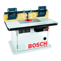
12.2 Wiring harness terminal diagram
12.2.1 Connection to actuation circuit board
PROTECT.
COMPRESS.PUMPPUMPOUT 1OUT 3OUT 4OUT 6OUT 7
OUT 8
LINE IN
TERRA
TERRA
BU
BN
YE/GN
YE/GN
BU
BN
YE/GN
BU
BN
YE/GN
BU
BN
YE/GN
BU
BN
YE/GN
BU
BN
YE/GN
BU
BN
YE/GN
BU
BN
YE/GN
BU
BN
YE/GN
BU
BN
YE/GN
POM1POM2OUT 1OUT 3OUT 4OUT 6 COMP
BU
BN
YE/GN
LINE
PROT
459790-7
OUT 7OUT 8
Fig. 33: Wiring harness connection to actuation circuit board
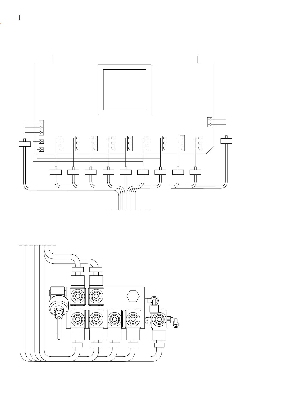
12.2.2 Connection to valve block
459790-6
POM2 OUT 1 OUT 4 OUT 3
POM2C OUT 1A
OUT 8
Fig. 34: Wiring harness connection to valve block

 Loading...