Robert Bosch GmbH
en 5ACS 500
1 689 975 197 (2006-09-22)
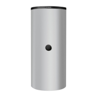
3.1.2 Cold chamber
Fig. 2: Component overview in cold chamber
1. Refrigerant flask (reservoir)
2. Scale
3. Vacuum pump
4. Processing unit
3.2 Component overview
3.2.1 Valve block
1
3 4 5 6
7 8 9 10 11
12
459790-4
2
Fig. 3: Valve block overview
1. Hose line for inlet and return
2. Solenoid valve for UV contrast medium injection phase
3. Solenoid valve (OUT L) for oil injection phase
4. Solenoid valve (OUT R) for filling phase
5. Solenoid valves (OUT A) for recovery/recycling phase
6. Solenoid valves (OUT B) for vacuum phase
7. Pressure sensor
8. Connection to vacuum pump
9. Connection to processing unit
10. Connection to refrigerant flask
11. Connection to oil separator
12. Non-return valve

 Loading...