Robert Bosch GmbH
en 27
ACS 500
1 689 975 197 (2006-09-22)
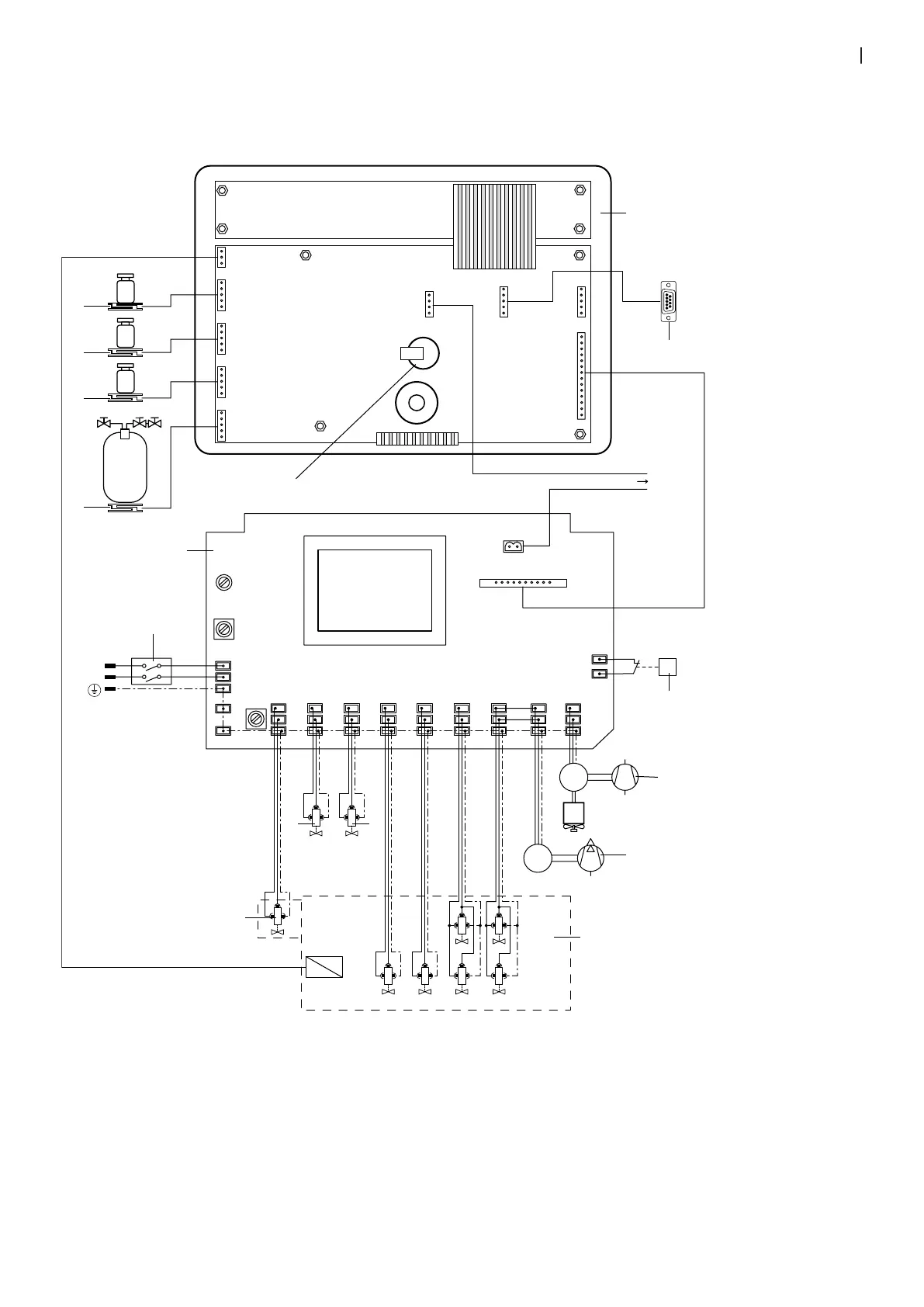
12. Electrical terminal diagram
12.1 General terminal diagram
DRUCKER
PRINTER
OUT C
OUT P
C
P
M
M
PROTECT.
PRINTER
COMPRESS. PUMP
J2
GND
V +18
GND
V +18
IN PMP
IN CMP
OUT HP
IN 7
IN 1
IN 3
IN 4
IN 6
IN 8
PUMP OUT 1 OUT 3 OUT 4 OUT 6 OUT 7 OUT 8
230 V
50/60 Hz
LINE IN
200 mA T
F2
TERRA
TERRA
F1
F3
OUT B OUT A OUT LOUT R
OUT S
BN
CN5 CN4
CN3
CN1
CN2
CN8
CN10
CN11
CN9
U
N
BU
GN/YE
P
GND
V +18
IN PMP
IN CMP
OUT HP
IN 7
IN 1
IN 3
IN 4
IN 6
4
P
U
11,9/15 bar (ACS 400)
16/19,5 bar (ACS 450)
4
5
3
2
6
7
8
9
1
10
OUT I
11
12
13
14
15
16
Fig. 32: General terminal diagram
10. Master switch
11. Actuation circuit board
12. Scale for refrigerant
13. Scale for oil injection
14. Scale for oil drain
15. Scale for UV contrast medium injection
16. Battery
1. Control/display unit
2. Interface for firmware download
3. Pressure switch
4. Compressor
5. Vacuum pump
6. Valve block
7. Solenoid valve for oil drain
8. Solenoid valve for connection of LP or HP terminal
9. Solenoid valve for UV contrast medium injection

 Loading...