D9412GV4/D7412GV4/D7212GV4 | Installation and Operation Guide | 7.0 Telephone Connections
Bosch Security Systems, Inc. | 3/12 | F01U266054-01 33
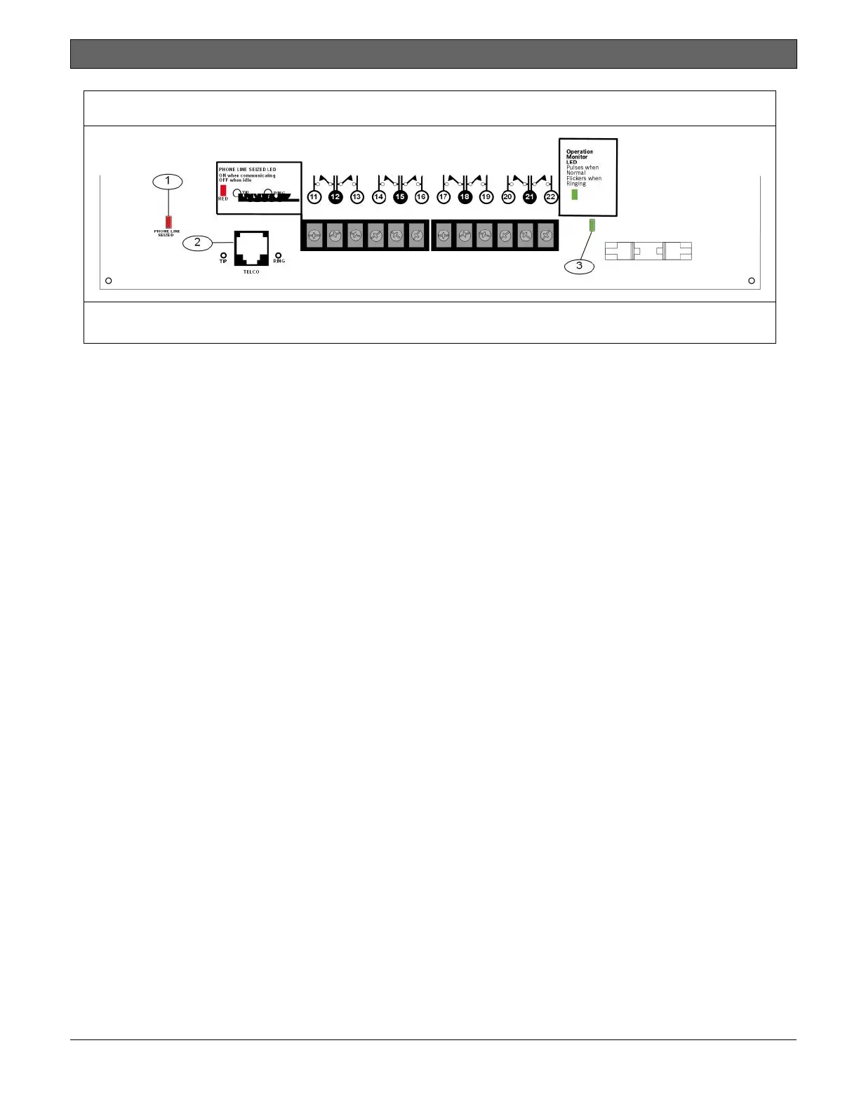
Figure 10: Phone Connector, Phone LED, and Operation Monitor LED Locations
1 - Phone LED (red)
2 - Telephone cord connector
3 - Operation Monitor LED (green)
7.5 Phone LED (Red)
The red Phone LED illuminates when the control
panel seizes the telephone line and remains
illuminated until the control panel returns the
telephone line. Refer to Figure 10 on page 33 for
the location of the red LED.
7.6 Operation Monitor LED (Green)
The green Operation Monitor LED indicates the
operation of the central processing unit (CPU).
When the CPU is operating normally, the LED
flashes 0.5 sec on, 0.5 sec off.
This green LED also serves as a ring indicator.
The Operation Monitor LED is located on the
lower right side (Figure 10 on page 33). When
there is ring voltage on the telephone line (the
telephone is ringing), the green LED flashes at a
faster rate for the duration of each ring. Ring
voltage must reach a minimum of 45 VAC before
the system detects it.
7.7 Dialing Format
The system can be programmed to use dual tone
multi-frequency (DTMF) or pulse dialing. Refer to
Phone Parameters in the
D9412GV4/D7412GV4/D7212GV4 Program Entry
Guide (P/N: F01U218312).
7.8 Telephone Line Monitor
The control panel has a built-in telephone line
monitor that tests the telephone line for voltage
and current. If the D928 Dual Phone Line
Switcher is used to connect two telephone lines
to the control panel, both lines are monitored.
The normal voltage on a telephone line is
approximately 48 VDC (24 VDC for some
telephone systems).
If the control panel senses trouble, it starts a
programmable telephone line trouble timer,
which continues to run as long as the monitor
detects trouble. It resets to zero when the
control panel senses a normal line. If the timer
reaches the delay time in the Phone Supervision
program item, it begins a telephone line trouble
response. Programming determines what the
response is. For programming information, refer
to Phone Parameters in the
D9412GV4/D7412GV4/D7212GV4 Program Entry
Guide (P/N: F01U218312).
Any time the control panel uses the telephone
line to make a call or is on-line with the remote
programming software (RPS), it stops monitoring
the telephone line during this process. When the
telephone line on the control panel is no longer in
use, it begins to monitor the telephone line again.
Bad Line Might Test OK: The telephone line
monitor uses voltage levels to test the status of
the telephone line. In some instances, a given
telephone line might be out of service without
affecting the voltage on the line. The telephone
line monitor cannot recognize this trouble
condition.

 Loading...


