D9412GV4/D7412GV4/D7212GV4 | Installation and Operation Guide | 9.0 Off-Board Points
Bosch Security Systems, Inc. | 3/12 | F01U266054-01 50
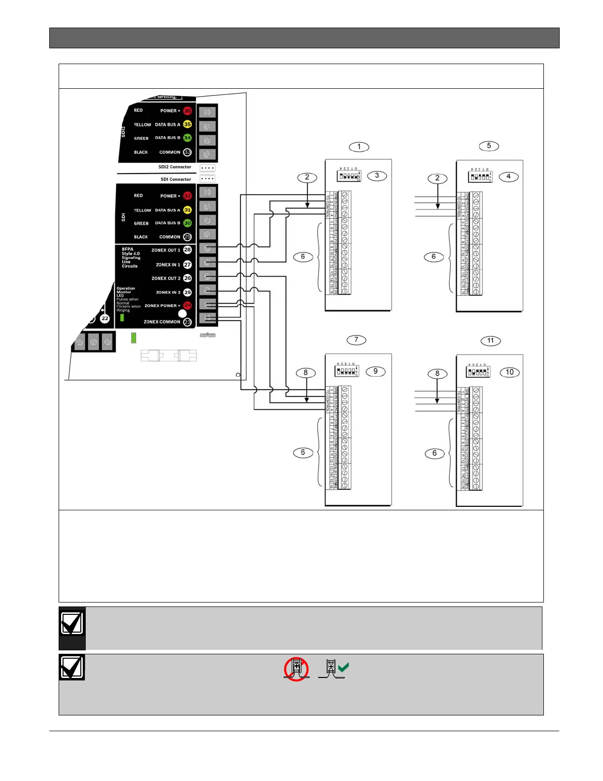
Figure 17: Connecting D8128D OctoPOPITs to the D9412GV4
1 - Zonex Bus 1, Switch 1 ON (Points 9 to 72)
2 - Bus 1
3 - First address on Zonex Bus 1
4 - Last address on Zonex Bus 1
5 - Zonex Bus 1, Switch 1 OFF (Points 73 to 127)
6 - Sensor loops
7 - Zonex Bus 2, Switch 1 ON (Points 129 to 192)
8 - Bus 2
9 - First address on Zonex Bus 2
10 - Last address on Zonex Bus 2
11 - Zonex Bus 2, Switch 1 OFF (Points 193 to 240)
Refer to Address Switches in Section 9.4.4 Setting the OctoPOPIT Switches on page 47 for
information about making these switch settings. Refer to Table 13 on page 48 for
information about setting Switch 5.
For system supervision, do not use looped wire terminals. Break the wire run to provide
supervision of the connections.

 Loading...


