EasyManuals Logo

Bosch D9412GV4 Installation And Operation Guide

Bosch D9412GV4
88 pages
To Next Page IconTo Next Page
To Previous Page IconTo Previous Page
Page #74 background imageLoading...
Page #74 background image
D9412GV4/D7412GV4/D7212GV4 | Installation and Operation Guide | 15.0 Accessory Connector
Bosch Security Systems, Inc. | 3/12 | F01U266054-01 74
15.0 Accessory Connector
Use the accessory connector to connect the
D9412GV4 or D7412GV4 control panel to the
D928 Dual Phone Line Switcher. The accessory
connector is on the bottom right corner of the
I/O board (Figure 32). The D928 lets the control
panel use two telephone lines to send reports.
Refer to Section 7.11 D928 Dual Phone Line
Switcher on page 34 for installation and operating
instructions.
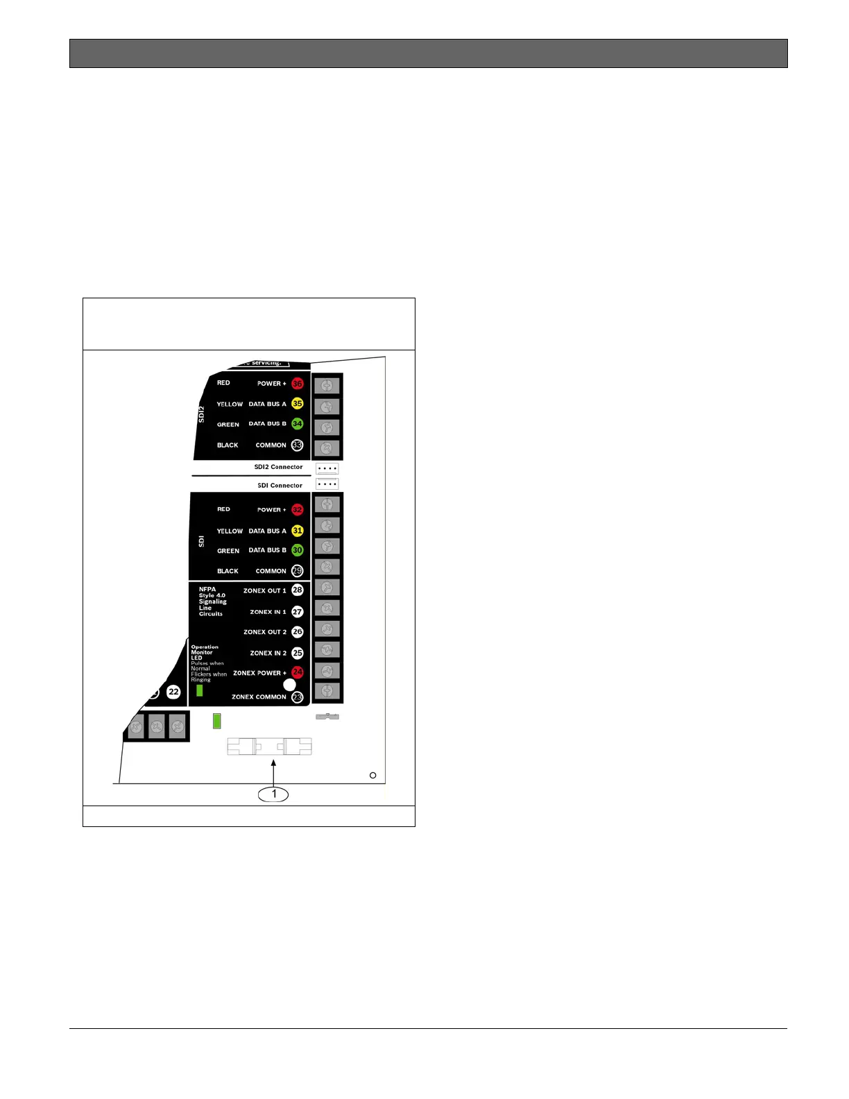
Figure 32: Accessory Connection on D9412GV4
and D7412GV4
1 - Accessory connector

Table of Contents

Other manuals for Bosch D9412GV4

Questions and Answers:

Question and Answer IconNeed help?

Do you have a question about the Bosch D9412GV4 and is the answer not in the manual?

Bosch D9412GV4 Specifications

General IconGeneral
Power Supply12 VDC
TypeControl Panel
ModelD9412GV4
ManufacturerBosch
Operating Temperature0°C to +49°C (+32°F to +120°F)
Compatible withConettix IP, GSM, GPRS, and POTS communicators

Related product manuals