D9412GV4/D7412GV4/D7212GV4 | Installation and Operation Guide | Appendix A: System Wiring Diagrams
Bosch Security Systems, Inc. | 3/12 | F01U266054-01 77
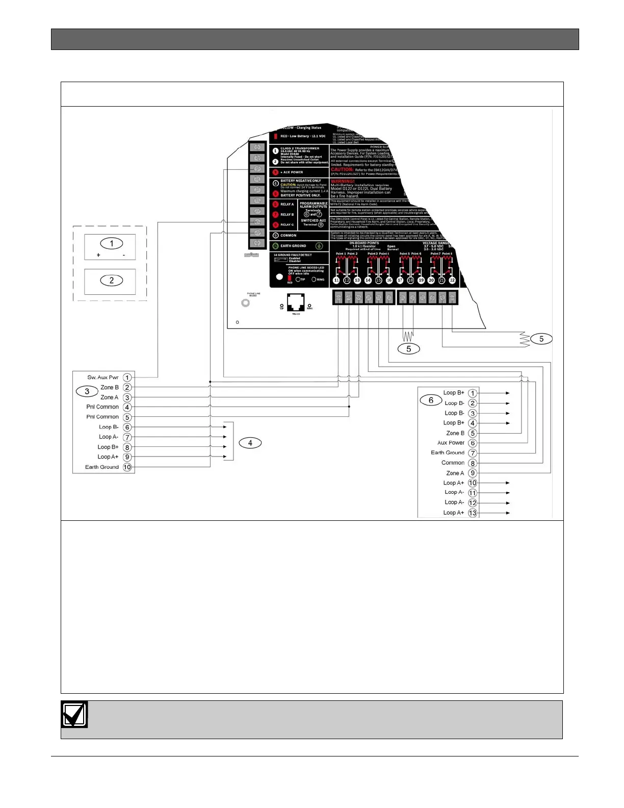
A.2 Input Points and Peripheral Devices Wiring Diagrams
Figure 35: D9412GV4/D7412GV4/D7212GV4 Input Points and Peripheral Devices System Wiring
1 - (Optional): For 24 V applications use a UL 1481
listed, regulated, power-limited 24 VDC power
supply with a D130 Relay Module. Refer to the
D130 Installation Instructions (P/N: F01U072455)
for correct wiring requirements.
2 - D130 Relay Module
3 - D125B Powered Loop Interface Module
4 - To UL Listed two-wire smoke detectors with a fire
rated EOL resistor. Refer to Two-Wire Smoke
Detectors in the
D9412GV4/D7412GV4/D7212GV4 Approved
Applications Compliance Guide (P/N:
F01U201525) for a listing of compatible two-wire
smoke detectors.
5 - 1k Ω EOL resistor (P/N: F01U033966): For
typical burglar alarm applications.
6 - D129 Dual Class A Initiation Circuit Module:
Provides optional Waterflow Alarm Retard
feature. Not suitable for two-wire smoke
detectors.
For D129, use zero retard except for waterflow devices.
All external connections except Terminal 5 (battery positive) are power limited.

 Loading...


