D9412GV4/D7412GV4/D7212GV4 | Installation and Operation Guide | 12.0 SDI Devices
Bosch Security Systems, Inc. | 3/12 | F01U266054-01 68
When a serial communication modules
is installed at an SDI Address, it cannot
be used for central station
communications.
UL requires that serial communication
modules be used for programming
only.
12.6 SDI Network Interface Modules
The GV4 Series Control Panels support up to four
network interface modules that provide
connection for two-way communication over
Ethernet networks. Up to two Bosch Security
Systems, Inc. DX4020 Network Interface Modules
can be installed on the SDI bus. Likewise, up to
two Bosch Security Systems, Inc. B420 Ethernet
Communication Modules can be installed on the
SDI2 bus. Refer to Section 13.5 B420
Ethernet Communication Module section for
details regarding the SDI2 network interface
modules.
For programming information on enhanced
communications, refer to the
D9412GV4/D7412GV4/D7212GV4 Program Entry
Guide (P/N: F01U218312).
The DX4020 can be installed on the SDI bus up to
305 m (1000 ft) from the control panel or
auxiliary power supply using 0.8 mm (22 AWG)
wire.
The ITS-DX4020-G GPRS/GSM IP Communicator
enables two-way IP or dialed communication over
a commercial GPRS/GSM network. Typical
applications are event reporting to a central
monitoring station and remote access to Bosch
intrusion control panels.
The ITS-DX4020-G GPRS/GSM IP Communicator
has two modes; GPRS uses Modem IIIa
2
; and
GSM uses Contact ID.
The B420 modules can be installed on the SDI
bus when configured to emulate DX4020
modules. Regardless of bus type, the modules
can be up to 305m (1000ft) from the control
panel or auxiliary power supply using 0.8 mm (22
AWG) wire.
For programming information refer to the
ITS-DX4020-G GPRS/GSM IP Communicator
Installation and Operation Guide (P/N:
F01U163066
).
12.6.1 Address Settings
The DX4020 has specific DIP switch settings for
SDI Addresses 88 and 92 when using the DX4020
for Remote Programming Software (RPS) or
enhanced communications in a local-area
network (LAN) or wide-area network (WAN)
environment. Refer to Figure 27 for the correct
switch settings.
12.6.2 Supervision
Supervision of Network Interface Modules at SDI
Addresses 88 and 92 are enabled automatically
when used to communicate with a central station
network receiver. Supervision ensures reliable
operation between the module and the control
panel.
If supervised and the module does not respond
to control panel supervision polls, then a system
fault message appears at the keypad. The report
to the receiver includes the address of the
troubled module indicating which module needs
service.
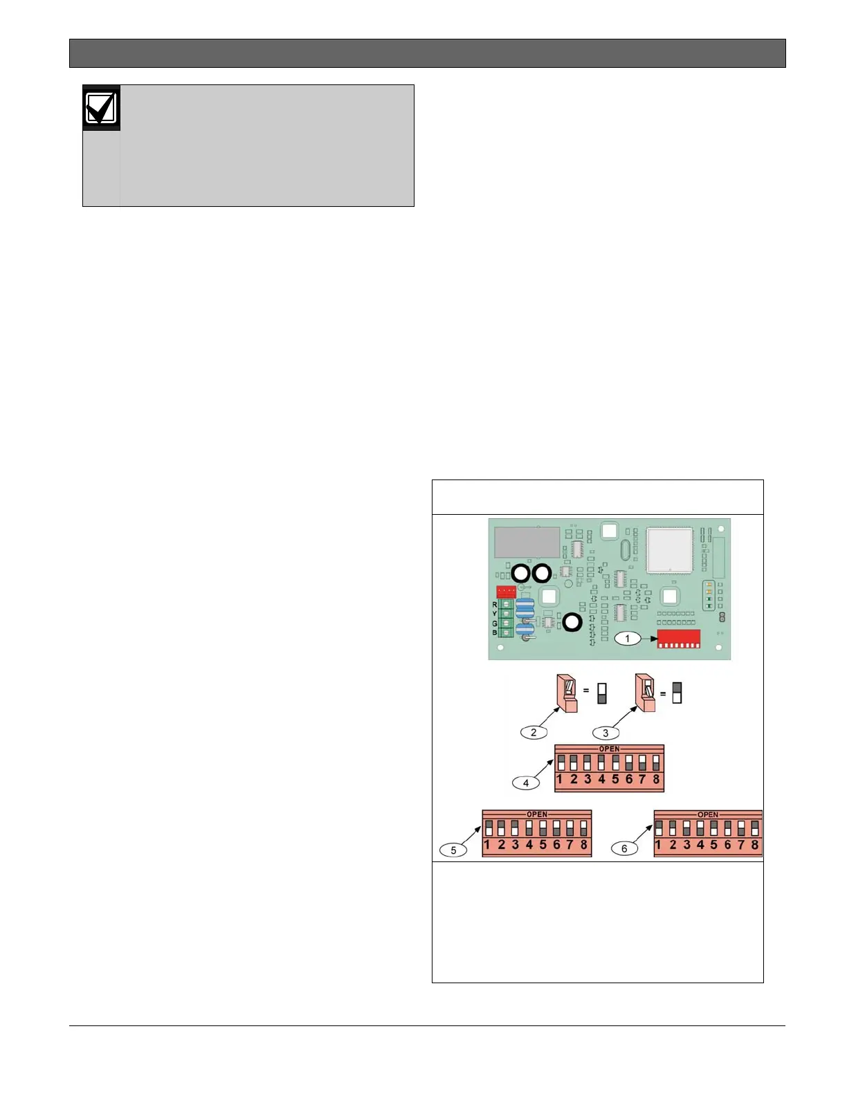
Figure 27: DX4020 DIP Switch Settings
1 - DIP Switches
2 - ON position
3 - OFF position
4 - SDI Address 80 switch settings
5 - SDI Address 88 switch settings
6 - SDI Address 92 switch settings

 Loading...


