1 689 979 672 2012-06-26| Robert Bosch GmbH
�0 | EPS 807 / 815 | Product descriptionen
�.5 Description of the unit
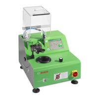
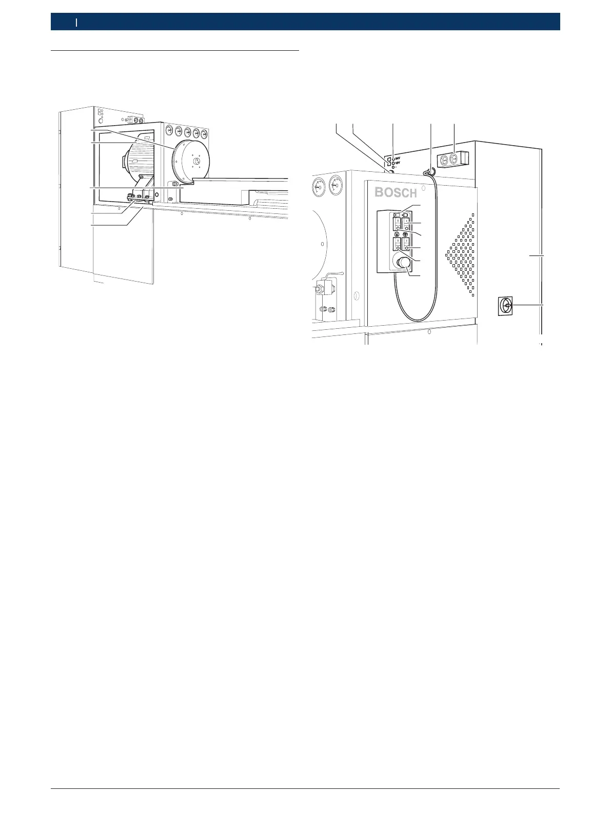
�.5.1 Drive
1
2
3
5
4
458735/1
The drive motor (2) and clamping bracket (3) are bolted
together through a rigid plate. The flywheel (1) is at-
tached directly to the shaft taper on the drive motor
(2). This drive unit is mounted in bearings on anti-vi-
bration mountings (4) in the test-bench frame (5). The
series 8 test benches feature a stepless, variable-speed
electronic drive. In technical terms, a field-controlled,
4-quadrant frequency converter with a vectorial control
loop is combined with a three-phase a.c. motor. This
drive motor (2) was designed to be used in conjunction
with injection-pump testing.
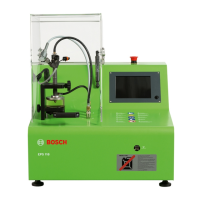
�.5.2 Control cabinet, control unit
All the electrical components and control elements re-
quired for operation are housed in the control cabinet.
2
1
9 10 11 12 13
3
4
5
6
7
8
458735/2
1 Control cabinet
2 Main switch
3 Emergency STOP switch
4 ON/OFF switch with indicator lamp for calibration-fluid heater
5 ON/OFF switch with indicator lamp for lubricating-oil pump
6 ON/OFF switch with indicator lamp for converter, calibration fluid
7 ON/OFF switch with indicator lamp for controller enable
8 Control unit
9 Connection for measuring system (MGT or KMA)
10 Automatic circuit-breakers for 12 and 24 volt / 7 amp (direct voltage)
11 Terminals for 12 and 24 volt / 7 amp (direct voltage)
12 Connection for control unit
13 2 x 230 volt / 2.5 amp socket (alternating voltage)
The control unit (8), featuring an Emergency STOP
switch and the ON/OFF switches for the units, can be
attached to either side of the EPS.
! Never connect two or more items of electrical equip-
ment (e.g. CRS 845 trigger unit, solenoid valve) to
the 12/24 V supply terminals (Pos.10) of the EPS, as
this could damage the electrical equipment!
Never disconnect or connect electrical equipment
with the EPSswitched on.
 Loading...