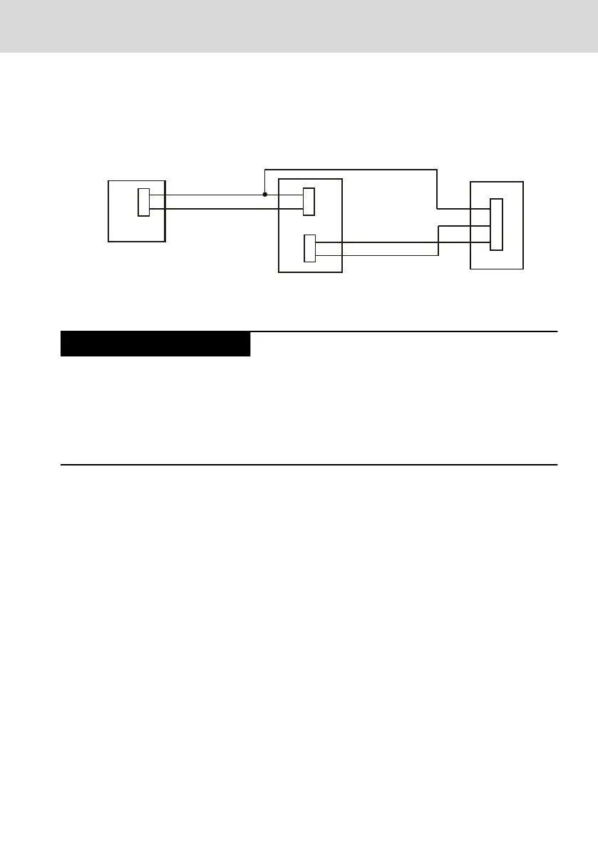
UPS without USB interface
To identify the connection of this UPS using the power supply electronics in the
control cabinet PC, connect the 24 V voltage (24V In) applied to the UPS input
to pin 3 of the X10 (U).
Control cabinet PC
UPS
→
230 V~
+
+
−
−
U
+
+
1
2
3
24 V
24 V
Out
24 V
In
X10
−
−
230 V → 24 V
External power supply unit
Fig. 10-15: Connecting an external UPS without communication to the control cabinet PC
Wrong initialization of the CDI interface and no
image output at the connected display VDP xx.3
if the input voltage has been switched on too
early
If the control cabinet PC is shut down under Windows and the 24 V input
voltage is switched off, the input voltage can only be switched on again when
the V
IN
LED is off.
10.3.3 Recommendation when mounting of CDI cables with long
lengths in an interference-prone environment
The CDI cable is a connection cable with RJ45 plug to connect the CDI interface
of the control cabinet PC to the remote operator display or the Y-repeater.
The mounting recommendations described in the following facilitate an
optimized signal transmission. In particular in case of great cable lengths and
distances between the control cabinet PC and the remote operator display,
ensure that the cable is installed correctly and that the shield is connected
correctly.
Cables routing
Comply with the following when routing the cables:
● Keep the maximum possible distance to interference-prone cables and lines
● Limit parallel routing with other lines
● Keep the maximum possible distance to sources of interference such as
drives and frequency converters
● Mechanical protection against tensile load and compressive load on the
cables
IndraControl VPB 40.4
37/57
Mounting, demounting and electric installation
R911376309_Edition 02 Bosch Rexroth AG

 Loading...